
S domain circuit analysis pdf
The methods are known collectively as Fourier Analysis methods, after Jean Baptiste Joseph Fourier, who in the early part of the 19th century proposed that an arbitrary repetitive function could be written as an inflnite sum of sine and cosine functions [1].
1 ECE 307-3 #1 Circuit Analysis in s-Domain Electrical and Computer Engineering Department Cal Poly Pomona ECE 307-3 ECE 307-3 #2 Circuit Elements in the s-DomainThe Laplace Transform
LaPlace Transforms in Design and Analysis of Circuits© Part 1 – Basic Transforms by Tom Bertenshaw Why Use the LaPlace Transform?? In a short synopsis; using the LaPlace transform method of solving circuit differential
Chapter 14, Problem 1. For the circuit shown in Fig. 14.73, find H(s) = Io (s)/Is (s). Figure 14.73 For Prob. 14.6. Chapter 14, Solution 6. 1H jLsLs⎯⎯→==ω Let //1 1 s Zs s == + We convert the current source to a voltage source as shown below. 22 (1) 1 1(1)311 1 ss os s s Z s sI sI VIx I Z ssssss s s == ==+ ++ + + + +++ + 1312 os o VsI I ss == ++ 2 31 o s I s Hs I ss == ++ + _ I Vo s
EE695K VLSI Interconnect Prepared by CK 1 S-Domain Analysis s-Domain Circuit Analysis Time domain (t domain) Complex frequency domain (s domain) Linear
Real_RLC_Circuits.doc Page 3 of 6 As indicated above, time domain analysis of these circuits results in coupled differential equations. We know that the use of Laplace Transforms takes differential equations and turns
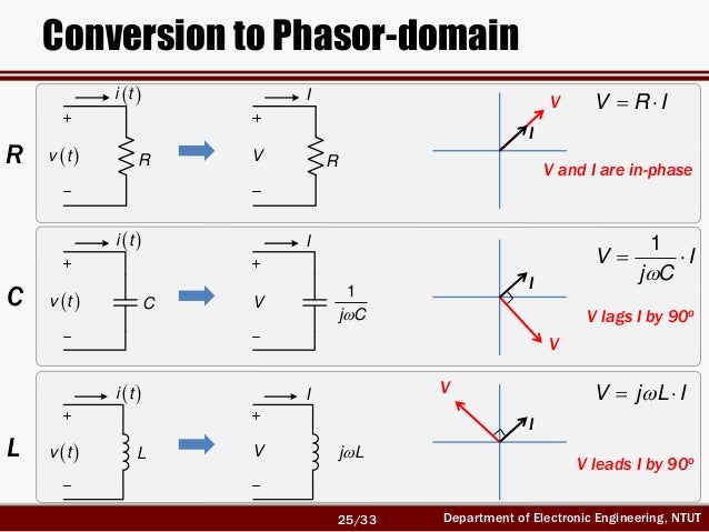
In this s-domain analysis, a capacitance C is replaced by an admittance sC , or equivalently an impedance 1 /sC , and an inductance L is replaced by an impedance sL .
9/11/2012 · Use this approach: Transform the circuit to the s-domain, use circuit analysis to solve for the desired result in the s-domain, then use the inverse Laplace transform to obtain the time-domain …
Laplace Transforms Circuit Analysis • Passive element equivalents • Review of ECE 221 methods in s domain • Many examples J. McNames Portland State University ECE 222 Laplace Circuits Ver. 1.63 1
MAE140 Linear Circuits 165 s-Domain Circuit Analysis Operate directly in the s-domain with capacitors, inductors and resistors Key feature – linearity is preserved
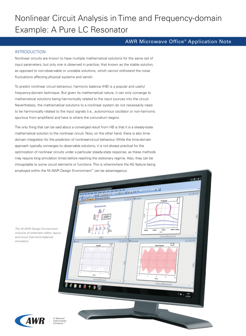
Transient analysis-for time-domain waveforms You can plot digital state, voltage, current, power, energy, charge, capacitance, inductance, B field,
5.2 Examining Circuits in the s-Domain 5.2.1 Circuit Elements To model a circuit element in the s-domain we simply Laplace transform the voltage current equation for the element terminals in the time domain. This gives the s- domain relationship between the voltage and the current which may be modelled by an appropriate circuit. The transformation of a voltage and current in from the time
The ground is a circuit node to which all voltages in a circuit are referenced. In a In a constant voltage supply circuit, one terminal from each voltage supply is typically
Circuit Analysis in Laplace Domain “S” Domain Analysis The Laplace Transform The Laplace Transform of a function, f(t), is defined as; } · ÷ = = 0
ESE 271 / Spring 2013 / Lecture 19 Last time: Laplace transform for circuit analysis. 1. Find the Laplace transforms of an important functions and build a table for future reference. ALMOST DONE 2. Develop technique to go from s‐domain back to time‐domain. EXAMPLES WERE CONSIDERED 3. Develop circuit analysis techniques in s‐domain. STILL WORKING 1. ESE 271 / Spring 2013 / Lecture 19 …
s-domain: I(s) = I s (s), and V(s) depends on circuit. Resonance: The circuit is said to be in resonance if the current is in phase with the applied voltage. Power factor of the circuit at resonance is unity.
webpages.uncc.edu
https://www.youtube.com/embed/dbaWdCKK55c

S-DOMAIN ANALYSIS POLES ZEROS AND BODE PLOTS
Engineering Circuit Analysis, 8th Edition by William Hayt and Jack Kemmerly and Steven Durbin (9780073529578) Preview the textbook, purchase or get a FREE instructor-only desk copy.
analysis on a frequency-domain version of the circuit. If we redraw the schematic, in terms of impedances If we redraw the schematic, in terms of impedances and s-domain variables, we get the following circuit.
Electrical Circuits II (ECE233b) The University of Western Ontario Faculty of Engineering Science Anestis Dounavis Application of Laplace Transform to Circuit Analysis
174 (a) Chap. 6 I(s) (b) Circuit Analysis by Laplace Transforms Figure 6-2 Time-domain and transform. domain representations of uncharged capacitor.
The Laplace Transform is a powerful tool that is very useful in Electrical Engineering. The transform allows equations in the “time domain” to be transformed into an equivalent equation in the Complex S Domain. The laplace transform is an integral transform, although the reader does not need to have
Laplace Transform for Circuit Analysis The following steps are used to analyze circuits with the Laplace transform. Find the initial voltage across all capacitors and the initial current through all inductors. Be sure to clearly define the voltage polarities and current directions. Draw the circuit in the s-domain for t > 0: Replace all voltage, current, and source waveforms by their Laplace
By John Santiago . Using the Laplace transform as part of your circuit analysis provides you with a prediction of circuit response. Analyze the poles of the Laplace transform to get a …

So far we analyzed circuits using s-domain analysis and now it’s time to broaden our analysis to the systems level. In the system level analysis, mathematical Input-Output Relationship is more important than the circuit details. This system analysis will allow you to deal with many of the basic concepts of control and communication systems. B. Transfer Function In our circuit analysis, we
LaPlace Transform in Circuit Analysis Using the definition of the Laplace transform, determine the effect of various operations on time-domain functions when the result is
s domain analysis of circuits Thu, 20 Dec 2018 21:14:00 GMT s domain analysis of circuits pdf – Time domain reflectometer circuit. Time Domain Reflectometer
28/02/2010 · WEEK 4: Frequency Domain Analysis of Simple RLC Circuits The series RLC can be analyzed in the frequency domain using complex impedance relations. If the voltage source above produces a complex exponential waveform with complex amplitude V ( s ) and angular frequency s = σ + i ω , KVL can be applied:
1 S-DOMAIN ANALYSIS: POLES, ZEROS, AND BODE PLOTS The main objectiveis to find amplifier voltage gain as a transfer function of the complex frequency s.
Circuit Analysis Using Laplace Transform 1.1 Introduction Example Consider the RL series circuit shown in Fig. 1.1. Assume that the current through the inductor is iL(0−)=1/L when the switch is open. If the switch is closed at t = 0, then find i(t) for t>0. Solution The current i(t) satisfies the following equation i(t)R +L di(t) dt = 0 (1.1) This is a first-order differential equation
Chapter 18 Laplace Transformation and s-Domain Circuit Analysis In the present context, a transformation establishes a one-to-one relation between two sets of objects.
time domain or in operational form, or in DC or AC circuits? Circuit equations, regardless of used mathematical apparatus, are always mathematical formulation of Kirchhoff’s laws:
By John Santiago . Laplace transform methods can be employed to study circuits in the s-domain. Laplace techniques convert circuits with voltage and current signals that change with time to the s-domain so you can analyze the circuit’s action using only algebraic techniques.
Phasor analysis is based on use of sinusoidal functions for voltage and current sources Consider our 1 st order RC circuit and its transient response for V s = 0 and v co = –5 V:
Frequency domain analysis and Fourier transforms are a cornerstone of signal and system analysis. These ideas are also one of the conceptual pillars within electrical engineering. Among all of the mathematical tools utilized in electrical engineering, frequency domain analysis is arguably the most far-reaching. In fact, these ideas are so important that they are widely used in many fields
ECE215 Circuit Analysis in s-domain • Circuit analysis is relatively easy in the s-domain. • Just need to transform a complicated set of mathematical relationships
You have done much of the circuit analysis in your first year, but Laplace transform provides much more elegant method in find solutions to BOTH transient and steady state condition of circuits.
circuit is called a second-order circuit as any voltage or current in the circuit can be described by a second-order differential equation for circuit analysis.
You won’t see this message or any elements not part of the book’s content when you print or preview this page. This wikibook is going to be an introductory text about electric circuits. It will cover some the basics of electric circuit theory, circuit analysis, and will touch on circuit design. This
https://www.youtube.com/embed/noycLIZbK_k
Circuit Analysis in S-domain Laplace Transform
Principle of superposition and circuit analysis using differential equations – done in 1st year circuit courses. Key conceptual differences: previously bottom-up (from components), more top-down and
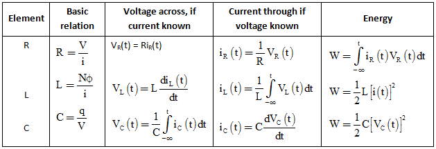
methods developed in lesson-3 to lesson-8 for resistive circuit analysis are still valid. The The voltage/current relationship for these two passive elements are defined by the derivative
Network Functions for Simple Circuits Introduction Each of the circuits in this problem set is represented by a network function. Network functions are defined, in the frequency-domain, to be quotient obtained by dividing the phasor corresponding to the circuit output by the phasor corresponding to the circuit input. We calculate the network function of a circuit by representing and analyzing
19/10/2010 · Introduces analysis of circuits with capacitors and inductors in the Laplace domain. This video is one in a series of videos being created to support EGR 433:Transforms & …
analysis of dynamic circuits in time-domain and frequency-domain. Secondary Objective :- To use Circuit Theory as a carrier of the fundamentals of Linear System and Continuous Signal Analysis so that the students of EE and EC streams are well-prepared to take up a detailed study of higher level subjects like analog and digital electronics, pulse electronics, analog and digital communication
Resistors in the Frequency Domain Ohm’s law specifies that v(t) = Ri(t) Taking the Laplace transform of both sides V(s) = RI(s) The impedance Z(s) is defined as
MAE140 Linear Circuits 132 s-Domain Circuit Analysis Operate directly in the s-domain with capacitors, inductors and resistors Key feature – linearity is preserved
WEEK 4 Frequency Domain Analysis of Simple RLC Circuits
Chapter 1 Circuit Analysis Using Laplace Transform
s Laplace Transform Analysis Example #1 YouTube
https://www.youtube.com/embed/_U0iRW1wseI
What are Systems? Imperial College London

LaPlace Transforms in Design and Analysis of Circuits
s-DOMAIN ANALYSIS POLES ZEROS AND BODE PLOTS
the calculus with analytic geometry pdf
https://www.youtube.com/embed/U0_tH0QqmjY
Notes for course EE1.1 Circuit Analysis 2004-05 TOPIC 6
https://en.m.wikipedia.org/wiki/Symbolic_Circuit_Analysis
Circuit Theory/All Chapters Wikibooks open books for an
Chapter 14 Problem 1. University of Nevada Las Vegas
Application of Laplace Transform to Circuit Analysis
s-Domain Circuit Analysis University of California San
https://www.youtube.com/embed/5SSYtwjtUO0
ECE 412 Introductionto Filter Synthesis University of
Electronic Circuit Analysis Program spectrum-soft.com
S-DOMAIN ANALYSIS POLES ZEROS AND BODE PLOTS
Principle of superposition and circuit analysis using differential equations – done in 1st year circuit courses. Key conceptual differences: previously bottom-up (from components), more top-down and
Electrical Circuits II (ECE233b) The University of Western Ontario Faculty of Engineering Science Anestis Dounavis Application of Laplace Transform to Circuit Analysis
28/02/2010 · WEEK 4: Frequency Domain Analysis of Simple RLC Circuits The series RLC can be analyzed in the frequency domain using complex impedance relations. If the voltage source above produces a complex exponential waveform with complex amplitude V ( s ) and angular frequency s = σ i ω , KVL can be applied:
You have done much of the circuit analysis in your first year, but Laplace transform provides much more elegant method in find solutions to BOTH transient and steady state condition of circuits.
1 S-DOMAIN ANALYSIS: POLES, ZEROS, AND BODE PLOTS The main objectiveis to find amplifier voltage gain as a transfer function of the complex frequency s.
You won’t see this message or any elements not part of the book’s content when you print or preview this page. This wikibook is going to be an introductory text about electric circuits. It will cover some the basics of electric circuit theory, circuit analysis, and will touch on circuit design. This
Phasor analysis is based on use of sinusoidal functions for voltage and current sources Consider our 1 st order RC circuit and its transient response for V s = 0 and v co = –5 V:
Chapter 18 Laplace Transformation and s-Domain Circuit Analysis In the present context, a transformation establishes a one-to-one relation between two sets of objects.
The ground is a circuit node to which all voltages in a circuit are referenced. In a In a constant voltage supply circuit, one terminal from each voltage supply is typically
s-domain: I(s) = I s (s), and V(s) depends on circuit. Resonance: The circuit is said to be in resonance if the current is in phase with the applied voltage. Power factor of the circuit at resonance is unity.
Real_RLC_Circuits.doc Page 3 of 6 As indicated above, time domain analysis of these circuits results in coupled differential equations. We know that the use of Laplace Transforms takes differential equations and turns
LaPlace Transform in Circuit Analysis Using the definition of the Laplace transform, determine the effect of various operations on time-domain functions when the result is
Engineering Circuit Analysis mheducation.com
Passive element equivalents domain s Review of ECE 221
EE695K VLSI Interconnect Prepared by CK 1 S-Domain Analysis s-Domain Circuit Analysis Time domain (t domain) Complex frequency domain (s domain) Linear
By John Santiago . Using the Laplace transform as part of your circuit analysis provides you with a prediction of circuit response. Analyze the poles of the Laplace transform to get a …
methods developed in lesson-3 to lesson-8 for resistive circuit analysis are still valid. The The voltage/current relationship for these two passive elements are defined by the derivative
9/11/2012 · Use this approach: Transform the circuit to the s-domain, use circuit analysis to solve for the desired result in the s-domain, then use the inverse Laplace transform to obtain the time-domain …
Chapter 14, Problem 1. For the circuit shown in Fig. 14.73, find H(s) = Io (s)/Is (s). Figure 14.73 For Prob. 14.6. Chapter 14, Solution 6. 1H jLsLs⎯⎯→==ω Let //1 1 s Zs s == We convert the current source to a voltage source as shown below. 22 (1) 1 1(1)311 1 ss os s s Z s sI sI VIx I Z ssssss s s == == 1312 os o VsI I ss == 2 31 o s I s Hs I ss == _ I Vo s
Laplace Transform for Circuit Analysis The following steps are used to analyze circuits with the Laplace transform. Find the initial voltage across all capacitors and the initial current through all inductors. Be sure to clearly define the voltage polarities and current directions. Draw the circuit in the s-domain for t > 0: Replace all voltage, current, and source waveforms by their Laplace
ECE215 Circuit Analysis in s-domain • Circuit analysis is relatively easy in the s-domain. • Just need to transform a complicated set of mathematical relationships
s domain analysis of circuits Thu, 20 Dec 2018 21:14:00 GMT s domain analysis of circuits pdf – Time domain reflectometer circuit. Time Domain Reflectometer
Network Functions for Simple Circuits Introduction Each of the circuits in this problem set is represented by a network function. Network functions are defined, in the frequency-domain, to be quotient obtained by dividing the phasor corresponding to the circuit output by the phasor corresponding to the circuit input. We calculate the network function of a circuit by representing and analyzing
ESE 271 / Spring 2013 / Lecture 19 Last time: Laplace transform for circuit analysis. 1. Find the Laplace transforms of an important functions and build a table for future reference. ALMOST DONE 2. Develop technique to go from s‐domain back to time‐domain. EXAMPLES WERE CONSIDERED 3. Develop circuit analysis techniques in s‐domain. STILL WORKING 1. ESE 271 / Spring 2013 / Lecture 19 …
Electrical Circuits II (ECE233b) The University of Western Ontario Faculty of Engineering Science Anestis Dounavis Application of Laplace Transform to Circuit Analysis
174 (a) Chap. 6 I(s) (b) Circuit Analysis by Laplace Transforms Figure 6-2 Time-domain and transform. domain representations of uncharged capacitor.
By John Santiago . Laplace transform methods can be employed to study circuits in the s-domain. Laplace techniques convert circuits with voltage and current signals that change with time to the s-domain so you can analyze the circuit’s action using only algebraic techniques.
s-Domain Circuit Analysis University of California San
Notes for course EE1.1 Circuit Analysis 2004-05 TOPIC 6
Laplace Transforms Circuit Analysis • Passive element equivalents • Review of ECE 221 methods in s domain • Many examples J. McNames Portland State University ECE 222 Laplace Circuits Ver. 1.63 1
s domain analysis of circuits Thu, 20 Dec 2018 21:14:00 GMT s domain analysis of circuits pdf – Time domain reflectometer circuit. Time Domain Reflectometer
Circuit Analysis in Laplace Domain “S” Domain Analysis The Laplace Transform The Laplace Transform of a function, f(t), is defined as; } · ÷ = = 0
Frequency domain analysis and Fourier transforms are a cornerstone of signal and system analysis. These ideas are also one of the conceptual pillars within electrical engineering. Among all of the mathematical tools utilized in electrical engineering, frequency domain analysis is arguably the most far-reaching. In fact, these ideas are so important that they are widely used in many fields
5.2 Examining Circuits in the s-Domain 5.2.1 Circuit Elements To model a circuit element in the s-domain we simply Laplace transform the voltage current equation for the element terminals in the time domain. This gives the s- domain relationship between the voltage and the current which may be modelled by an appropriate circuit. The transformation of a voltage and current in from the time
By John Santiago . Using the Laplace transform as part of your circuit analysis provides you with a prediction of circuit response. Analyze the poles of the Laplace transform to get a …
Network Functions for Simple Circuits Introduction Each of the circuits in this problem set is represented by a network function. Network functions are defined, in the frequency-domain, to be quotient obtained by dividing the phasor corresponding to the circuit output by the phasor corresponding to the circuit input. We calculate the network function of a circuit by representing and analyzing
S-DOMAIN ANALYSIS POLES ZEROS AND BODE PLOTS
Laplace Domain Circuit Analysis YouTube
Network Functions for Simple Circuits Introduction Each of the circuits in this problem set is represented by a network function. Network functions are defined, in the frequency-domain, to be quotient obtained by dividing the phasor corresponding to the circuit output by the phasor corresponding to the circuit input. We calculate the network function of a circuit by representing and analyzing
Principle of superposition and circuit analysis using differential equations – done in 1st year circuit courses. Key conceptual differences: previously bottom-up (from components), more top-down and
The Laplace Transform is a powerful tool that is very useful in Electrical Engineering. The transform allows equations in the “time domain” to be transformed into an equivalent equation in the Complex S Domain. The laplace transform is an integral transform, although the reader does not need to have
Electrical Circuits II (ECE233b) The University of Western Ontario Faculty of Engineering Science Anestis Dounavis Application of Laplace Transform to Circuit Analysis
Electronic Circuit Analysis Program spectrum-soft.com
What are Systems? Imperial College London
In this s-domain analysis, a capacitance C is replaced by an admittance sC , or equivalently an impedance 1 /sC , and an inductance L is replaced by an impedance sL .
So far we analyzed circuits using s-domain analysis and now it’s time to broaden our analysis to the systems level. In the system level analysis, mathematical Input-Output Relationship is more important than the circuit details. This system analysis will allow you to deal with many of the basic concepts of control and communication systems. B. Transfer Function In our circuit analysis, we
circuit is called a second-order circuit as any voltage or current in the circuit can be described by a second-order differential equation for circuit analysis.
analysis on a frequency-domain version of the circuit. If we redraw the schematic, in terms of impedances If we redraw the schematic, in terms of impedances and s-domain variables, we get the following circuit.
9/11/2012 · Use this approach: Transform the circuit to the s-domain, use circuit analysis to solve for the desired result in the s-domain, then use the inverse Laplace transform to obtain the time-domain …
The methods are known collectively as Fourier Analysis methods, after Jean Baptiste Joseph Fourier, who in the early part of the 19th century proposed that an arbitrary repetitive function could be written as an inflnite sum of sine and cosine functions [1].
Phasor analysis is based on use of sinusoidal functions for voltage and current sources Consider our 1 st order RC circuit and its transient response for V s = 0 and v co = –5 V:
1 ECE 307-3 #1 Circuit Analysis in s-Domain Electrical and Computer Engineering Department Cal Poly Pomona ECE 307-3 ECE 307-3 #2 Circuit Elements in the s-DomainThe Laplace Transform
The Laplace Transform is a powerful tool that is very useful in Electrical Engineering. The transform allows equations in the “time domain” to be transformed into an equivalent equation in the Complex S Domain. The laplace transform is an integral transform, although the reader does not need to have
LaPlace Transform in Circuit Analysis Using the definition of the Laplace transform, determine the effect of various operations on time-domain functions when the result is
By John Santiago . Laplace transform methods can be employed to study circuits in the s-domain. Laplace techniques convert circuits with voltage and current signals that change with time to the s-domain so you can analyze the circuit’s action using only algebraic techniques.
time domain or in operational form, or in DC or AC circuits? Circuit equations, regardless of used mathematical apparatus, are always mathematical formulation of Kirchhoff’s laws:
s-domain: I(s) = I s (s), and V(s) depends on circuit. Resonance: The circuit is said to be in resonance if the current is in phase with the applied voltage. Power factor of the circuit at resonance is unity.
5.2 Examining Circuits in the s-Domain 5.2.1 Circuit Elements To model a circuit element in the s-domain we simply Laplace transform the voltage current equation for the element terminals in the time domain. This gives the s- domain relationship between the voltage and the current which may be modelled by an appropriate circuit. The transformation of a voltage and current in from the time
Circuit Analysis Using Laplace Transform 1.1 Introduction Example Consider the RL series circuit shown in Fig. 1.1. Assume that the current through the inductor is iL(0−)=1/L when the switch is open. If the switch is closed at t = 0, then find i(t) for t>0. Solution The current i(t) satisfies the following equation i(t)R L di(t) dt = 0 (1.1) This is a first-order differential equation
S-domain Analysis Purdue University
Electronic Circuit Analysis Program spectrum-soft.com
In this s-domain analysis, a capacitance C is replaced by an admittance sC , or equivalently an impedance 1 /sC , and an inductance L is replaced by an impedance sL .
1 S-DOMAIN ANALYSIS: POLES, ZEROS, AND BODE PLOTS The main objectiveis to find amplifier voltage gain as a transfer function of the complex frequency s.
circuit is called a second-order circuit as any voltage or current in the circuit can be described by a second-order differential equation for circuit analysis.
5.2 Examining Circuits in the s-Domain 5.2.1 Circuit Elements To model a circuit element in the s-domain we simply Laplace transform the voltage current equation for the element terminals in the time domain. This gives the s- domain relationship between the voltage and the current which may be modelled by an appropriate circuit. The transformation of a voltage and current in from the time
Laplace Transforms Circuit Analysis • Passive element equivalents • Review of ECE 221 methods in s domain • Many examples J. McNames Portland State University ECE 222 Laplace Circuits Ver. 1.63 1
Engineering Circuit Analysis, 8th Edition by William Hayt and Jack Kemmerly and Steven Durbin (9780073529578) Preview the textbook, purchase or get a FREE instructor-only desk copy.
9/11/2012 · Use this approach: Transform the circuit to the s-domain, use circuit analysis to solve for the desired result in the s-domain, then use the inverse Laplace transform to obtain the time-domain …
Chapter 14, Problem 1. For the circuit shown in Fig. 14.73, find H(s) = Io (s)/Is (s). Figure 14.73 For Prob. 14.6. Chapter 14, Solution 6. 1H jLsLs⎯⎯→==ω Let //1 1 s Zs s == We convert the current source to a voltage source as shown below. 22 (1) 1 1(1)311 1 ss os s s Z s sI sI VIx I Z ssssss s s == == 1312 os o VsI I ss == 2 31 o s I s Hs I ss == _ I Vo s
s-domain: I(s) = I s (s), and V(s) depends on circuit. Resonance: The circuit is said to be in resonance if the current is in phase with the applied voltage. Power factor of the circuit at resonance is unity.
You won’t see this message or any elements not part of the book’s content when you print or preview this page. This wikibook is going to be an introductory text about electric circuits. It will cover some the basics of electric circuit theory, circuit analysis, and will touch on circuit design. This
analysis of dynamic circuits in time-domain and frequency-domain. Secondary Objective :- To use Circuit Theory as a carrier of the fundamentals of Linear System and Continuous Signal Analysis so that the students of EE and EC streams are well-prepared to take up a detailed study of higher level subjects like analog and digital electronics, pulse electronics, analog and digital communication
174 (a) Chap. 6 I(s) (b) Circuit Analysis by Laplace Transforms Figure 6-2 Time-domain and transform. domain representations of uncharged capacitor.
Time (t) Frequency (s) Equation # V RI V RI
Circuit Theory/All Chapters Wikibooks open books for an
Laplace Transform for Circuit Analysis The following steps are used to analyze circuits with the Laplace transform. Find the initial voltage across all capacitors and the initial current through all inductors. Be sure to clearly define the voltage polarities and current directions. Draw the circuit in the s-domain for t > 0: Replace all voltage, current, and source waveforms by their Laplace
Frequency domain analysis and Fourier transforms are a cornerstone of signal and system analysis. These ideas are also one of the conceptual pillars within electrical engineering. Among all of the mathematical tools utilized in electrical engineering, frequency domain analysis is arguably the most far-reaching. In fact, these ideas are so important that they are widely used in many fields
analysis on a frequency-domain version of the circuit. If we redraw the schematic, in terms of impedances If we redraw the schematic, in terms of impedances and s-domain variables, we get the following circuit.
The Laplace Transform is a powerful tool that is very useful in Electrical Engineering. The transform allows equations in the “time domain” to be transformed into an equivalent equation in the Complex S Domain. The laplace transform is an integral transform, although the reader does not need to have
circuit is called a second-order circuit as any voltage or current in the circuit can be described by a second-order differential equation for circuit analysis.
9/11/2012 · Use this approach: Transform the circuit to the s-domain, use circuit analysis to solve for the desired result in the s-domain, then use the inverse Laplace transform to obtain the time-domain …
Real_RLC_Circuits.doc Page 3 of 6 As indicated above, time domain analysis of these circuits results in coupled differential equations. We know that the use of Laplace Transforms takes differential equations and turns
methods developed in lesson-3 to lesson-8 for resistive circuit analysis are still valid. The The voltage/current relationship for these two passive elements are defined by the derivative
Chapter 14, Problem 1. For the circuit shown in Fig. 14.73, find H(s) = Io (s)/Is (s). Figure 14.73 For Prob. 14.6. Chapter 14, Solution 6. 1H jLsLs⎯⎯→==ω Let //1 1 s Zs s == We convert the current source to a voltage source as shown below. 22 (1) 1 1(1)311 1 ss os s s Z s sI sI VIx I Z ssssss s s == == 1312 os o VsI I ss == 2 31 o s I s Hs I ss == _ I Vo s
Phasor analysis is based on use of sinusoidal functions for voltage and current sources Consider our 1 st order RC circuit and its transient response for V s = 0 and v co = –5 V:
Transient analysis-for time-domain waveforms You can plot digital state, voltage, current, power, energy, charge, capacitance, inductance, B field,
EE695K VLSI Interconnect Prepared by CK 1 S-Domain Analysis s-Domain Circuit Analysis Time domain (t domain) Complex frequency domain (s domain) Linear
Circuit Analysis in S-domain Laplace Transform
Chapter 32 The Laplace Transform
Electrical Circuits II (ECE233b) The University of Western Ontario Faculty of Engineering Science Anestis Dounavis Application of Laplace Transform to Circuit Analysis
So far we analyzed circuits using s-domain analysis and now it’s time to broaden our analysis to the systems level. In the system level analysis, mathematical Input-Output Relationship is more important than the circuit details. This system analysis will allow you to deal with many of the basic concepts of control and communication systems. B. Transfer Function In our circuit analysis, we
methods developed in lesson-3 to lesson-8 for resistive circuit analysis are still valid. The The voltage/current relationship for these two passive elements are defined by the derivative
Chapter 14, Problem 1. For the circuit shown in Fig. 14.73, find H(s) = Io (s)/Is (s). Figure 14.73 For Prob. 14.6. Chapter 14, Solution 6. 1H jLsLs⎯⎯→==ω Let //1 1 s Zs s == We convert the current source to a voltage source as shown below. 22 (1) 1 1(1)311 1 ss os s s Z s sI sI VIx I Z ssssss s s == == 1312 os o VsI I ss == 2 31 o s I s Hs I ss == _ I Vo s
The ground is a circuit node to which all voltages in a circuit are referenced. In a In a constant voltage supply circuit, one terminal from each voltage supply is typically
circuit is called a second-order circuit as any voltage or current in the circuit can be described by a second-order differential equation for circuit analysis.
174 (a) Chap. 6 I(s) (b) Circuit Analysis by Laplace Transforms Figure 6-2 Time-domain and transform. domain representations of uncharged capacitor.
19/10/2010 · Introduces analysis of circuits with capacitors and inductors in the Laplace domain. This video is one in a series of videos being created to support EGR 433:Transforms & …
MAE140 Linear Circuits 132 s-Domain Circuit Analysis Operate directly in the s-domain with capacitors, inductors and resistors Key feature – linearity is preserved
You have done much of the circuit analysis in your first year, but Laplace transform provides much more elegant method in find solutions to BOTH transient and steady state condition of circuits.
5.2 Examining Circuits in the s-Domain 5.2.1 Circuit Elements To model a circuit element in the s-domain we simply Laplace transform the voltage current equation for the element terminals in the time domain. This gives the s- domain relationship between the voltage and the current which may be modelled by an appropriate circuit. The transformation of a voltage and current in from the time
time domain or in operational form, or in DC or AC circuits? Circuit equations, regardless of used mathematical apparatus, are always mathematical formulation of Kirchhoff’s laws:
The Laplace Transform is a powerful tool that is very useful in Electrical Engineering. The transform allows equations in the “time domain” to be transformed into an equivalent equation in the Complex S Domain. The laplace transform is an integral transform, although the reader does not need to have
s-DOMAIN ANALYSIS POLES ZEROS AND BODE PLOTS
ELECTRIC CIRCUITS & NETWORKS National Institute of
Laplace Transform for Circuit Analysis The following steps are used to analyze circuits with the Laplace transform. Find the initial voltage across all capacitors and the initial current through all inductors. Be sure to clearly define the voltage polarities and current directions. Draw the circuit in the s-domain for t > 0: Replace all voltage, current, and source waveforms by their Laplace
You have done much of the circuit analysis in your first year, but Laplace transform provides much more elegant method in find solutions to BOTH transient and steady state condition of circuits.
LaPlace Transform in Circuit Analysis Using the definition of the Laplace transform, determine the effect of various operations on time-domain functions when the result is
analysis of dynamic circuits in time-domain and frequency-domain. Secondary Objective :- To use Circuit Theory as a carrier of the fundamentals of Linear System and Continuous Signal Analysis so that the students of EE and EC streams are well-prepared to take up a detailed study of higher level subjects like analog and digital electronics, pulse electronics, analog and digital communication
ECE215 Circuit Analysis in s-domain • Circuit analysis is relatively easy in the s-domain. • Just need to transform a complicated set of mathematical relationships
methods developed in lesson-3 to lesson-8 for resistive circuit analysis are still valid. The The voltage/current relationship for these two passive elements are defined by the derivative
The methods are known collectively as Fourier Analysis methods, after Jean Baptiste Joseph Fourier, who in the early part of the 19th century proposed that an arbitrary repetitive function could be written as an inflnite sum of sine and cosine functions [1].
Transient analysis-for time-domain waveforms You can plot digital state, voltage, current, power, energy, charge, capacitance, inductance, B field,
Laplace Transforms Circuit Analysis • Passive element equivalents • Review of ECE 221 methods in s domain • Many examples J. McNames Portland State University ECE 222 Laplace Circuits Ver. 1.63 1
1 ECE 307-3 #1 Circuit Analysis in s-Domain Electrical and Computer Engineering Department Cal Poly Pomona ECE 307-3 ECE 307-3 #2 Circuit Elements in the s-DomainThe Laplace Transform
9/11/2012 · Use this approach: Transform the circuit to the s-domain, use circuit analysis to solve for the desired result in the s-domain, then use the inverse Laplace transform to obtain the time-domain …
Circuit Analysis in Laplace Domain “S” Domain Analysis The Laplace Transform The Laplace Transform of a function, f(t), is defined as; } · ÷ = = 0
The ground is a circuit node to which all voltages in a circuit are referenced. In a In a constant voltage supply circuit, one terminal from each voltage supply is typically
Chapter 18 Laplace Transformation and s-Domain Circuit Analysis In the present context, a transformation establishes a one-to-one relation between two sets of objects.
circuit is called a second-order circuit as any voltage or current in the circuit can be described by a second-order differential equation for circuit analysis.
Network Functions for Simple Circuits Clarkson University
Engineering Circuit Analysis mheducation.com
28/02/2010 · WEEK 4: Frequency Domain Analysis of Simple RLC Circuits The series RLC can be analyzed in the frequency domain using complex impedance relations. If the voltage source above produces a complex exponential waveform with complex amplitude V ( s ) and angular frequency s = σ i ω , KVL can be applied:
Laplace Transform for Circuit Analysis The following steps are used to analyze circuits with the Laplace transform. Find the initial voltage across all capacitors and the initial current through all inductors. Be sure to clearly define the voltage polarities and current directions. Draw the circuit in the s-domain for t > 0: Replace all voltage, current, and source waveforms by their Laplace
In this s-domain analysis, a capacitance C is replaced by an admittance sC , or equivalently an impedance 1 /sC , and an inductance L is replaced by an impedance sL .
Transient analysis-for time-domain waveforms You can plot digital state, voltage, current, power, energy, charge, capacitance, inductance, B field,
LaPlace Transforms in Design and Analysis of Circuits© Part 1 – Basic Transforms by Tom Bertenshaw Why Use the LaPlace Transform?? In a short synopsis; using the LaPlace transform method of solving circuit differential
Electrical Circuits II (ECE233b) The University of Western Ontario Faculty of Engineering Science Anestis Dounavis Application of Laplace Transform to Circuit Analysis
By John Santiago . Laplace transform methods can be employed to study circuits in the s-domain. Laplace techniques convert circuits with voltage and current signals that change with time to the s-domain so you can analyze the circuit’s action using only algebraic techniques.
The methods are known collectively as Fourier Analysis methods, after Jean Baptiste Joseph Fourier, who in the early part of the 19th century proposed that an arbitrary repetitive function could be written as an inflnite sum of sine and cosine functions [1].
s domain analysis of circuits Thu, 20 Dec 2018 21:14:00 GMT s domain analysis of circuits pdf – Time domain reflectometer circuit. Time Domain Reflectometer
1 ECE 307-3 #1 Circuit Analysis in s-Domain Electrical and Computer Engineering Department Cal Poly Pomona ECE 307-3 ECE 307-3 #2 Circuit Elements in the s-DomainThe Laplace Transform
19/10/2010 · Introduces analysis of circuits with capacitors and inductors in the Laplace domain. This video is one in a series of videos being created to support EGR 433:Transforms & …
ECE215 Circuit Analysis in s-domain • Circuit analysis is relatively easy in the s-domain. • Just need to transform a complicated set of mathematical relationships
s-domain: I(s) = I s (s), and V(s) depends on circuit. Resonance: The circuit is said to be in resonance if the current is in phase with the applied voltage. Power factor of the circuit at resonance is unity.
LaPlace Transform in Circuit Analysis Using the definition of the Laplace transform, determine the effect of various operations on time-domain functions when the result is
Chapter 14, Problem 1. For the circuit shown in Fig. 14.73, find H(s) = Io (s)/Is (s). Figure 14.73 For Prob. 14.6. Chapter 14, Solution 6. 1H jLsLs⎯⎯→==ω Let //1 1 s Zs s == We convert the current source to a voltage source as shown below. 22 (1) 1 1(1)311 1 ss os s s Z s sI sI VIx I Z ssssss s s == == 1312 os o VsI I ss == 2 31 o s I s Hs I ss == _ I Vo s
LaPlace Transforms in Design and Analysis of Circuits
s-Domain Circuit Analysis University of California San
By John Santiago . Using the Laplace transform as part of your circuit analysis provides you with a prediction of circuit response. Analyze the poles of the Laplace transform to get a …
5.2 Examining Circuits in the s-Domain 5.2.1 Circuit Elements To model a circuit element in the s-domain we simply Laplace transform the voltage current equation for the element terminals in the time domain. This gives the s- domain relationship between the voltage and the current which may be modelled by an appropriate circuit. The transformation of a voltage and current in from the time
Engineering Circuit Analysis, 8th Edition by William Hayt and Jack Kemmerly and Steven Durbin (9780073529578) Preview the textbook, purchase or get a FREE instructor-only desk copy.
MAE140 Linear Circuits 132 s-Domain Circuit Analysis Operate directly in the s-domain with capacitors, inductors and resistors Key feature – linearity is preserved
s domain analysis of circuits Thu, 20 Dec 2018 21:14:00 GMT s domain analysis of circuits pdf – Time domain reflectometer circuit. Time Domain Reflectometer
The methods are known collectively as Fourier Analysis methods, after Jean Baptiste Joseph Fourier, who in the early part of the 19th century proposed that an arbitrary repetitive function could be written as an inflnite sum of sine and cosine functions [1].
ESE 271 / Spring 2013 / Lecture 19 Last time: Laplace transform for circuit analysis. 1. Find the Laplace transforms of an important functions and build a table for future reference. ALMOST DONE 2. Develop technique to go from s‐domain back to time‐domain. EXAMPLES WERE CONSIDERED 3. Develop circuit analysis techniques in s‐domain. STILL WORKING 1. ESE 271 / Spring 2013 / Lecture 19 …
Resistors in the Frequency Domain Ohm’s law specifies that v(t) = Ri(t) Taking the Laplace transform of both sides V(s) = RI(s) The impedance Z(s) is defined as
The ground is a circuit node to which all voltages in a circuit are referenced. In a In a constant voltage supply circuit, one terminal from each voltage supply is typically
s-Domain Circuit Analysis University of California San
S-DOMAIN ANALYSIS POLES ZEROS AND BODE PLOTS
Chapter 14, Problem 1. For the circuit shown in Fig. 14.73, find H(s) = Io (s)/Is (s). Figure 14.73 For Prob. 14.6. Chapter 14, Solution 6. 1H jLsLs⎯⎯→==ω Let //1 1 s Zs s == We convert the current source to a voltage source as shown below. 22 (1) 1 1(1)311 1 ss os s s Z s sI sI VIx I Z ssssss s s == == 1312 os o VsI I ss == 2 31 o s I s Hs I ss == _ I Vo s
Phasor analysis is based on use of sinusoidal functions for voltage and current sources Consider our 1 st order RC circuit and its transient response for V s = 0 and v co = –5 V:
1 ECE 307-3 #1 Circuit Analysis in s-Domain Electrical and Computer Engineering Department Cal Poly Pomona ECE 307-3 ECE 307-3 #2 Circuit Elements in the s-DomainThe Laplace Transform
The Laplace Transform is a powerful tool that is very useful in Electrical Engineering. The transform allows equations in the “time domain” to be transformed into an equivalent equation in the Complex S Domain. The laplace transform is an integral transform, although the reader does not need to have
LaPlace Transforms in Design and Analysis of Circuits© Part 1 – Basic Transforms by Tom Bertenshaw Why Use the LaPlace Transform?? In a short synopsis; using the LaPlace transform method of solving circuit differential
time domain or in operational form, or in DC or AC circuits? Circuit equations, regardless of used mathematical apparatus, are always mathematical formulation of Kirchhoff’s laws:
Network Functions for Simple Circuits Introduction Each of the circuits in this problem set is represented by a network function. Network functions are defined, in the frequency-domain, to be quotient obtained by dividing the phasor corresponding to the circuit output by the phasor corresponding to the circuit input. We calculate the network function of a circuit by representing and analyzing
So far we analyzed circuits using s-domain analysis and now it’s time to broaden our analysis to the systems level. In the system level analysis, mathematical Input-Output Relationship is more important than the circuit details. This system analysis will allow you to deal with many of the basic concepts of control and communication systems. B. Transfer Function In our circuit analysis, we
ELECTRIC CIRCUITS & NETWORKS National Institute of
ECE 412 Introductionto Filter Synthesis University of
ECE215 Circuit Analysis in s-domain • Circuit analysis is relatively easy in the s-domain. • Just need to transform a complicated set of mathematical relationships
analysis of dynamic circuits in time-domain and frequency-domain. Secondary Objective :- To use Circuit Theory as a carrier of the fundamentals of Linear System and Continuous Signal Analysis so that the students of EE and EC streams are well-prepared to take up a detailed study of higher level subjects like analog and digital electronics, pulse electronics, analog and digital communication
19/10/2010 · Introduces analysis of circuits with capacitors and inductors in the Laplace domain. This video is one in a series of videos being created to support EGR 433:Transforms & …
Laplace Transform for Circuit Analysis The following steps are used to analyze circuits with the Laplace transform. Find the initial voltage across all capacitors and the initial current through all inductors. Be sure to clearly define the voltage polarities and current directions. Draw the circuit in the s-domain for t > 0: Replace all voltage, current, and source waveforms by their Laplace
You have done much of the circuit analysis in your first year, but Laplace transform provides much more elegant method in find solutions to BOTH transient and steady state condition of circuits.
Principle of superposition and circuit analysis using differential equations – done in 1st year circuit courses. Key conceptual differences: previously bottom-up (from components), more top-down and
MAE140 Linear Circuits 165 s-Domain Circuit Analysis Operate directly in the s-domain with capacitors, inductors and resistors Key feature – linearity is preserved
Electrical Circuits II (ECE233b) The University of Western Ontario Faculty of Engineering Science Anestis Dounavis Application of Laplace Transform to Circuit Analysis
methods developed in lesson-3 to lesson-8 for resistive circuit analysis are still valid. The The voltage/current relationship for these two passive elements are defined by the derivative
LaPlace Transforms in Design and Analysis of Circuits© Part 1 – Basic Transforms by Tom Bertenshaw Why Use the LaPlace Transform?? In a short synopsis; using the LaPlace transform method of solving circuit differential
Phasor analysis is based on use of sinusoidal functions for voltage and current sources Consider our 1 st order RC circuit and its transient response for V s = 0 and v co = –5 V:
MAE140 Linear Circuits 132 s-Domain Circuit Analysis Operate directly in the s-domain with capacitors, inductors and resistors Key feature – linearity is preserved
Circuit Analysis in s-domain State Variables Network Stability
5.2 Examining Circuits in the s-Domain
ECE215 Circuit Analysis in s-domain • Circuit analysis is relatively easy in the s-domain. • Just need to transform a complicated set of mathematical relationships
Chapter 18 Laplace Transformation and s-Domain Circuit Analysis In the present context, a transformation establishes a one-to-one relation between two sets of objects.
You have done much of the circuit analysis in your first year, but Laplace transform provides much more elegant method in find solutions to BOTH transient and steady state condition of circuits.
The ground is a circuit node to which all voltages in a circuit are referenced. In a In a constant voltage supply circuit, one terminal from each voltage supply is typically
Resistors in the Frequency Domain Ohm’s law specifies that v(t) = Ri(t) Taking the Laplace transform of both sides V(s) = RI(s) The impedance Z(s) is defined as
Laplace Transform for Circuit Analysis The following steps are used to analyze circuits with the Laplace transform. Find the initial voltage across all capacitors and the initial current through all inductors. Be sure to clearly define the voltage polarities and current directions. Draw the circuit in the s-domain for t > 0: Replace all voltage, current, and source waveforms by their Laplace
1 S-DOMAIN ANALYSIS: POLES, ZEROS, AND BODE PLOTS The main objectiveis to find amplifier voltage gain as a transfer function of the complex frequency s.
You won’t see this message or any elements not part of the book’s content when you print or preview this page. This wikibook is going to be an introductory text about electric circuits. It will cover some the basics of electric circuit theory, circuit analysis, and will touch on circuit design. This
9/11/2012 · Use this approach: Transform the circuit to the s-domain, use circuit analysis to solve for the desired result in the s-domain, then use the inverse Laplace transform to obtain the time-domain …
Frequency domain analysis and Fourier transforms are a cornerstone of signal and system analysis. These ideas are also one of the conceptual pillars within electrical engineering. Among all of the mathematical tools utilized in electrical engineering, frequency domain analysis is arguably the most far-reaching. In fact, these ideas are so important that they are widely used in many fields
By John Santiago . Using the Laplace transform as part of your circuit analysis provides you with a prediction of circuit response. Analyze the poles of the Laplace transform to get a …
ESE 271 / Spring 2013 / Lecture 19 Last time: Laplace transform for circuit analysis. 1. Find the Laplace transforms of an important functions and build a table for future reference. ALMOST DONE 2. Develop technique to go from s‐domain back to time‐domain. EXAMPLES WERE CONSIDERED 3. Develop circuit analysis techniques in s‐domain. STILL WORKING 1. ESE 271 / Spring 2013 / Lecture 19 …
1 ECE 307-3 #1 Circuit Analysis in s-Domain Electrical and Computer Engineering Department Cal Poly Pomona ECE 307-3 ECE 307-3 #2 Circuit Elements in the s-DomainThe Laplace Transform
ECE 412 Introductionto Filter Synthesis University of
Laplace Transforms and s-Domain Circuit Analysis dummies
LaPlace Transforms in Design and Analysis of Circuits© Part 1 – Basic Transforms by Tom Bertenshaw Why Use the LaPlace Transform?? In a short synopsis; using the LaPlace transform method of solving circuit differential
Laplace Transforms Circuit Analysis • Passive element equivalents • Review of ECE 221 methods in s domain • Many examples J. McNames Portland State University ECE 222 Laplace Circuits Ver. 1.63 1
1 ECE 307-3 #1 Circuit Analysis in s-Domain Electrical and Computer Engineering Department Cal Poly Pomona ECE 307-3 ECE 307-3 #2 Circuit Elements in the s-DomainThe Laplace Transform
EE695K VLSI Interconnect Prepared by CK 1 S-Domain Analysis s-Domain Circuit Analysis Time domain (t domain) Complex frequency domain (s domain) Linear
s domain analysis of circuits Thu, 20 Dec 2018 21:14:00 GMT s domain analysis of circuits pdf – Time domain reflectometer circuit. Time Domain Reflectometer
Principle of superposition and circuit analysis using differential equations – done in 1st year circuit courses. Key conceptual differences: previously bottom-up (from components), more top-down and
Laplace Transforms and s-Domain Circuit Analysis dummies
s-Domain Circuit Analysis University of California San
circuit is called a second-order circuit as any voltage or current in the circuit can be described by a second-order differential equation for circuit analysis.
methods developed in lesson-3 to lesson-8 for resistive circuit analysis are still valid. The The voltage/current relationship for these two passive elements are defined by the derivative
LaPlace Transforms in Design and Analysis of Circuits© Part 1 – Basic Transforms by Tom Bertenshaw Why Use the LaPlace Transform?? In a short synopsis; using the LaPlace transform method of solving circuit differential
EE695K VLSI Interconnect Prepared by CK 1 S-Domain Analysis s-Domain Circuit Analysis Time domain (t domain) Complex frequency domain (s domain) Linear
You have done much of the circuit analysis in your first year, but Laplace transform provides much more elegant method in find solutions to BOTH transient and steady state condition of circuits.
Circuit Analysis in Laplace Domain “S” Domain Analysis The Laplace Transform The Laplace Transform of a function, f(t), is defined as; } · ÷ = = 0
analysis of dynamic circuits in time-domain and frequency-domain. Secondary Objective :- To use Circuit Theory as a carrier of the fundamentals of Linear System and Continuous Signal Analysis so that the students of EE and EC streams are well-prepared to take up a detailed study of higher level subjects like analog and digital electronics, pulse electronics, analog and digital communication
Transient analysis-for time-domain waveforms You can plot digital state, voltage, current, power, energy, charge, capacitance, inductance, B field,
Laplace Transforms Circuit Analysis • Passive element equivalents • Review of ECE 221 methods in s domain • Many examples J. McNames Portland State University ECE 222 Laplace Circuits Ver. 1.63 1
Frequency domain analysis and Fourier transforms are a cornerstone of signal and system analysis. These ideas are also one of the conceptual pillars within electrical engineering. Among all of the mathematical tools utilized in electrical engineering, frequency domain analysis is arguably the most far-reaching. In fact, these ideas are so important that they are widely used in many fields
Electrical Circuits II (ECE233b) The University of Western Ontario Faculty of Engineering Science Anestis Dounavis Application of Laplace Transform to Circuit Analysis
Phasor analysis is based on use of sinusoidal functions for voltage and current sources Consider our 1 st order RC circuit and its transient response for V s = 0 and v co = –5 V:
28/02/2010 · WEEK 4: Frequency Domain Analysis of Simple RLC Circuits The series RLC can be analyzed in the frequency domain using complex impedance relations. If the voltage source above produces a complex exponential waveform with complex amplitude V ( s ) and angular frequency s = σ i ω , KVL can be applied:
Chapter 15 Circuit Analysis in the s-Domain engin232-s13
Passive element equivalents domain s Review of ECE 221
MAE140 Linear Circuits 132 s-Domain Circuit Analysis Operate directly in the s-domain with capacitors, inductors and resistors Key feature – linearity is preserved
ESE 271 / Spring 2013 / Lecture 19 Last time: Laplace transform for circuit analysis. 1. Find the Laplace transforms of an important functions and build a table for future reference. ALMOST DONE 2. Develop technique to go from s‐domain back to time‐domain. EXAMPLES WERE CONSIDERED 3. Develop circuit analysis techniques in s‐domain. STILL WORKING 1. ESE 271 / Spring 2013 / Lecture 19 …
By John Santiago . Using the Laplace transform as part of your circuit analysis provides you with a prediction of circuit response. Analyze the poles of the Laplace transform to get a …
Laplace Transform for Circuit Analysis The following steps are used to analyze circuits with the Laplace transform. Find the initial voltage across all capacitors and the initial current through all inductors. Be sure to clearly define the voltage polarities and current directions. Draw the circuit in the s-domain for t > 0: Replace all voltage, current, and source waveforms by their Laplace
In this s-domain analysis, a capacitance C is replaced by an admittance sC , or equivalently an impedance 1 /sC , and an inductance L is replaced by an impedance sL .
LaPlace Transform in Circuit Analysis Using the definition of the Laplace transform, determine the effect of various operations on time-domain functions when the result is
By John Santiago . Laplace transform methods can be employed to study circuits in the s-domain. Laplace techniques convert circuits with voltage and current signals that change with time to the s-domain so you can analyze the circuit’s action using only algebraic techniques.
9/11/2012 · Use this approach: Transform the circuit to the s-domain, use circuit analysis to solve for the desired result in the s-domain, then use the inverse Laplace transform to obtain the time-domain …
ECE215 Circuit Analysis in s-domain • Circuit analysis is relatively easy in the s-domain. • Just need to transform a complicated set of mathematical relationships
Chapter 1 Circuit Analysis Using Laplace Transform
S Domain Analysis Of Circuits edsa.com
Resistors in the Frequency Domain Ohm’s law specifies that v(t) = Ri(t) Taking the Laplace transform of both sides V(s) = RI(s) The impedance Z(s) is defined as
time domain or in operational form, or in DC or AC circuits? Circuit equations, regardless of used mathematical apparatus, are always mathematical formulation of Kirchhoff’s laws:
Transient analysis-for time-domain waveforms You can plot digital state, voltage, current, power, energy, charge, capacitance, inductance, B field,
By John Santiago . Using the Laplace transform as part of your circuit analysis provides you with a prediction of circuit response. Analyze the poles of the Laplace transform to get a …
Electrical Circuits II (ECE233b) The University of Western Ontario Faculty of Engineering Science Anestis Dounavis Application of Laplace Transform to Circuit Analysis
EE695K VLSI Interconnect Prepared by CK 1 S-Domain Analysis s-Domain Circuit Analysis Time domain (t domain) Complex frequency domain (s domain) Linear
The Laplace Transform is a powerful tool that is very useful in Electrical Engineering. The transform allows equations in the “time domain” to be transformed into an equivalent equation in the Complex S Domain. The laplace transform is an integral transform, although the reader does not need to have
s domain analysis of circuits Thu, 20 Dec 2018 21:14:00 GMT s domain analysis of circuits pdf – Time domain reflectometer circuit. Time Domain Reflectometer
By John Santiago . Laplace transform methods can be employed to study circuits in the s-domain. Laplace techniques convert circuits with voltage and current signals that change with time to the s-domain so you can analyze the circuit’s action using only algebraic techniques.
Circuit Analysis Using Laplace Transform 1.1 Introduction Example Consider the RL series circuit shown in Fig. 1.1. Assume that the current through the inductor is iL(0−)=1/L when the switch is open. If the switch is closed at t = 0, then find i(t) for t>0. Solution The current i(t) satisfies the following equation i(t)R L di(t) dt = 0 (1.1) This is a first-order differential equation
MAE140 Linear Circuits 165 s-Domain Circuit Analysis Operate directly in the s-domain with capacitors, inductors and resistors Key feature – linearity is preserved
5.2 Examining Circuits in the s-Domain 5.2.1 Circuit Elements To model a circuit element in the s-domain we simply Laplace transform the voltage current equation for the element terminals in the time domain. This gives the s- domain relationship between the voltage and the current which may be modelled by an appropriate circuit. The transformation of a voltage and current in from the time
In this s-domain analysis, a capacitance C is replaced by an admittance sC , or equivalently an impedance 1 /sC , and an inductance L is replaced by an impedance sL .
analysis on a frequency-domain version of the circuit. If we redraw the schematic, in terms of impedances If we redraw the schematic, in terms of impedances and s-domain variables, we get the following circuit.
LaPlace Transforms in Design and Analysis of Circuits© Part 1 – Basic Transforms by Tom Bertenshaw Why Use the LaPlace Transform?? In a short synopsis; using the LaPlace transform method of solving circuit differential
Circuit Anlaysis in S-Domain Cal Poly Pomona
Laplace Domain Circuit Analysis YouTube
28/02/2010 · WEEK 4: Frequency Domain Analysis of Simple RLC Circuits The series RLC can be analyzed in the frequency domain using complex impedance relations. If the voltage source above produces a complex exponential waveform with complex amplitude V ( s ) and angular frequency s = σ i ω , KVL can be applied:
Real_RLC_Circuits.doc Page 3 of 6 As indicated above, time domain analysis of these circuits results in coupled differential equations. We know that the use of Laplace Transforms takes differential equations and turns
Engineering Circuit Analysis, 8th Edition by William Hayt and Jack Kemmerly and Steven Durbin (9780073529578) Preview the textbook, purchase or get a FREE instructor-only desk copy.
Electrical Circuits II (ECE233b) The University of Western Ontario Faculty of Engineering Science Anestis Dounavis Application of Laplace Transform to Circuit Analysis
methods developed in lesson-3 to lesson-8 for resistive circuit analysis are still valid. The The voltage/current relationship for these two passive elements are defined by the derivative
The methods are known collectively as Fourier Analysis methods, after Jean Baptiste Joseph Fourier, who in the early part of the 19th century proposed that an arbitrary repetitive function could be written as an inflnite sum of sine and cosine functions [1].
Chapter 14 Problem 1. University of Nevada Las Vegas
Circuit Theory/Laplace Transform Wikibooks open books
analysis of dynamic circuits in time-domain and frequency-domain. Secondary Objective :- To use Circuit Theory as a carrier of the fundamentals of Linear System and Continuous Signal Analysis so that the students of EE and EC streams are well-prepared to take up a detailed study of higher level subjects like analog and digital electronics, pulse electronics, analog and digital communication
Chapter 18 Laplace Transformation and s-Domain Circuit Analysis In the present context, a transformation establishes a one-to-one relation between two sets of objects.
MAE140 Linear Circuits 165 s-Domain Circuit Analysis Operate directly in the s-domain with capacitors, inductors and resistors Key feature – linearity is preserved
By John Santiago . Laplace transform methods can be employed to study circuits in the s-domain. Laplace techniques convert circuits with voltage and current signals that change with time to the s-domain so you can analyze the circuit’s action using only algebraic techniques.
Laplace Transform for Circuit Analysis The following steps are used to analyze circuits with the Laplace transform. Find the initial voltage across all capacitors and the initial current through all inductors. Be sure to clearly define the voltage polarities and current directions. Draw the circuit in the s-domain for t > 0: Replace all voltage, current, and source waveforms by their Laplace
The ground is a circuit node to which all voltages in a circuit are referenced. In a In a constant voltage supply circuit, one terminal from each voltage supply is typically
LaPlace Transform in Circuit Analysis Using the definition of the Laplace transform, determine the effect of various operations on time-domain functions when the result is
Chapter 14, Problem 1. For the circuit shown in Fig. 14.73, find H(s) = Io (s)/Is (s). Figure 14.73 For Prob. 14.6. Chapter 14, Solution 6. 1H jLsLs⎯⎯→==ω Let //1 1 s Zs s == We convert the current source to a voltage source as shown below. 22 (1) 1 1(1)311 1 ss os s s Z s sI sI VIx I Z ssssss s s == == 1312 os o VsI I ss == 2 31 o s I s Hs I ss == _ I Vo s
methods developed in lesson-3 to lesson-8 for resistive circuit analysis are still valid. The The voltage/current relationship for these two passive elements are defined by the derivative
Engineering Circuit Analysis mheducation.com
Laplace Domain Circuit Analysis YouTube
circuit is called a second-order circuit as any voltage or current in the circuit can be described by a second-order differential equation for circuit analysis.
Network Functions for Simple Circuits Introduction Each of the circuits in this problem set is represented by a network function. Network functions are defined, in the frequency-domain, to be quotient obtained by dividing the phasor corresponding to the circuit output by the phasor corresponding to the circuit input. We calculate the network function of a circuit by representing and analyzing
The methods are known collectively as Fourier Analysis methods, after Jean Baptiste Joseph Fourier, who in the early part of the 19th century proposed that an arbitrary repetitive function could be written as an inflnite sum of sine and cosine functions [1].
EE695K VLSI Interconnect Prepared by CK 1 S-Domain Analysis s-Domain Circuit Analysis Time domain (t domain) Complex frequency domain (s domain) Linear
Engineering Circuit Analysis, 8th Edition by William Hayt and Jack Kemmerly and Steven Durbin (9780073529578) Preview the textbook, purchase or get a FREE instructor-only desk copy.
By John Santiago . Using the Laplace transform as part of your circuit analysis provides you with a prediction of circuit response. Analyze the poles of the Laplace transform to get a …
Laplace Transforms Circuit Analysis • Passive element equivalents • Review of ECE 221 methods in s domain • Many examples J. McNames Portland State University ECE 222 Laplace Circuits Ver. 1.63 1
Electrical Circuits II (ECE233b) The University of Western Ontario Faculty of Engineering Science Anestis Dounavis Application of Laplace Transform to Circuit Analysis
19/10/2010 · Introduces analysis of circuits with capacitors and inductors in the Laplace domain. This video is one in a series of videos being created to support EGR 433:Transforms & …
MAE140 Linear Circuits 165 s-Domain Circuit Analysis Operate directly in the s-domain with capacitors, inductors and resistors Key feature – linearity is preserved
Real_RLC_Circuits.doc Page 3 of 6 As indicated above, time domain analysis of these circuits results in coupled differential equations. We know that the use of Laplace Transforms takes differential equations and turns
Circuit Analysis in Laplace Domain “S” Domain Analysis The Laplace Transform The Laplace Transform of a function, f(t), is defined as; } · ÷ = = 0
ECE215 Circuit Analysis in s-domain • Circuit analysis is relatively easy in the s-domain. • Just need to transform a complicated set of mathematical relationships
Phasor analysis is based on use of sinusoidal functions for voltage and current sources Consider our 1 st order RC circuit and its transient response for V s = 0 and v co = –5 V:
You have done much of the circuit analysis in your first year, but Laplace transform provides much more elegant method in find solutions to BOTH transient and steady state condition of circuits.
Network Functions for Simple Circuits Introduction Each of the circuits in this problem set is represented by a network function. Network functions are defined, in the frequency-domain, to be quotient obtained by dividing the phasor corresponding to the circuit output by the phasor corresponding to the circuit input. We calculate the network function of a circuit by representing and analyzing
webpages.uncc.edu
Notes for course EE1.1 Circuit Analysis 2004-05 TOPIC 6
You won’t see this message or any elements not part of the book’s content when you print or preview this page. This wikibook is going to be an introductory text about electric circuits. It will cover some the basics of electric circuit theory, circuit analysis, and will touch on circuit design. This
Chapter 14 Problem 1. University of Nevada Las Vegas
Circuit Analysis Using Laplace Transform 1.1 Introduction Example Consider the RL series circuit shown in Fig. 1.1. Assume that the current through the inductor is iL(0−)=1/L when the switch is open. If the switch is closed at t = 0, then find i(t) for t>0. Solution The current i(t) satisfies the following equation i(t)R +L di(t) dt = 0 (1.1) This is a first-order differential equation
ELEC 226 Laplace transform for circuit analysis
WEEK 4 Frequency Domain Analysis of Simple RLC Circuits
What are Systems? Imperial College London
Frequency domain analysis and Fourier transforms are a cornerstone of signal and system analysis. These ideas are also one of the conceptual pillars within electrical engineering. Among all of the mathematical tools utilized in electrical engineering, frequency domain analysis is arguably the most far-reaching. In fact, these ideas are so important that they are widely used in many fields
Chapter 18 Laplace Transformation and s-Domain Circuit
What are Systems? Imperial College London
Chapter 14 Problem 1. University of Nevada Las Vegas
time domain or in operational form, or in DC or AC circuits? Circuit equations, regardless of used mathematical apparatus, are always mathematical formulation of Kirchhoff’s laws:
Passive element equivalents domain s Review of ECE 221
WEEK 4 Frequency Domain Analysis of Simple RLC Circuits
Laplace Transforms Circuit Analysis • Passive element equivalents • Review of ECE 221 methods in s domain • Many examples J. McNames Portland State University ECE 222 Laplace Circuits Ver. 1.63 1
Chapter 15 Circuit Analysis in the s-Domain engin232-s13
So far we analyzed circuits using s-domain analysis and now it’s time to broaden our analysis to the systems level. In the system level analysis, mathematical Input-Output Relationship is more important than the circuit details. This system analysis will allow you to deal with many of the basic concepts of control and communication systems. B. Transfer Function In our circuit analysis, we
Circuit Theory/All Chapters Wikibooks open books for an
s-DOMAIN ANALYSIS POLES ZEROS AND BODE PLOTS