
Turning moment diagram and flywheel pdf
THE FLYWHEEL-18-The moment of inertia, I, is determined by imagining that the body is divided into a number of infinitesimal elements of mass /mi each at a distance ri from the axis of rotation.
Free online beam calculator for generating the reactions, calculating the deflection of a steel or wood beam, drawing the shear and moment diagrams for the …
In a turning moment diagram, the variations of energy above and below the mean resisting torque line is called a) fluctuation of energy b) maximum fluctuation of energy c) coefficient of fluctuation of energy d) none of the mentioned View Answer. Answer: a Explanation: The fluctuation of energy may be determined by the turning moment diagram for one complete cycle of operation.The variations
Show transcribed image text 1. The mass of flywheel of an engine is 6.6 tonnes and the radius of gyration is 1.9 metres. It is found from the turning moment diagram that the fluctuation of energy is …
16.1. Introduction Turning moment diagram = graphical representation of turning moment or crank-effort for various positions of the crank 12/25/2015
Turning moment diagram (TMD) graphical representation of turning moment or crank-effort for various positions of the crank 10/29/2018 Mohammad Suliman Abuhaiba, Ph.D., PE
Turning Moment Diagram and Flywheel 1. Turning moment diagram & Flywheel Prepared by: RONAK D. SONI Assistant Professor 2. The turning moment diagram (also known as crank effort diagram) is the graphical representation of the turning moment or crank-effort for various positions of the crank. TURNING MOMENT DIAGRAMS Turning moment diagram for single cylinder double …
Bridges vs. Buildings • Bridges are owned by the public – (+) Can institute changes to bridge engineering relatively quick (e.g. LRFD) – (-) Focus is primarily on lowest initial cost,
What is Turning Moment Diagram (TMD) for 4-Stroke Engines in Flywheel & Governors, TOM, Mechanical Engineering, GATE video for GATE is made by best teachers who have written some of the best books of GATE.
Structural Axial, Shear and Bending Moments Positive Internal Forces Acting on a Portal Frame 2 Recall from mechanics of mater- ials that the internal forces P (generic axial), V (shear) and M (moment) represent resultants of the stress distribution acting on the cross section of the beam. Internal Axial Force (P) ≡ equal in magnitude but opposite in direction to the algebraic sum (resultant
14. Turning Moment Diagrams and Flywheel: 14.1 Turning moment diagram: The turning moment diagram (also known as crank representation of the turning moment Figure 1. The total area under the curve represents the work done by the crankshaft during the cycle. If the resisting torque is constant, this is represented by the line the mean engine torque. Between points torque and the crank shaft
flywheel is connected to the crank shaft it stores the energy when in excess and deliver when engine req it.
9 Turning Moment Diagram, Flywheel Yes Yes Turning Moment Diagram, Flywheel Turning Moment Diagram, Flywheel MCQ Long. and Trans.Vibrations Yes Yes Long. and Trans.Vibrations Long. and Trans.Vibrations MCQ 11 Production Engg. Metal Cutting Yes Yes Metal Cutting(Theory) Metal Cutting(MCQ) 12 Inventory control Yes Yes ForCasting Yes Yes 13 MathMatics Matrix Yes …
Moment. The turning effect of a force is known as the moment. It is the product of the force multiplied by the perpendicular distance from the line of action of …
Slope-Deflection Method Examples . Example 1 Determine the moments at B and D, then draw the moment diagram. Assume A and C are pinned and B and D are fixed connected.
Turning Moment Diagram & Flywheel – Download as Powerpoint Presentation (.ppt), PDF File (.pdf), Text File (.txt) or view presentation slides online.
Flywheel Torque Physical Quantities
https://www.youtube.com/embed/dsvKsfcbIFI
Turning Moment Diagrams Theory Of Machines – Engineering
tutorial – flywheels and turning moment diagrams This work covers elements of the syllabus for the Edexcel module 21722P HNC/D Mechanical Principles OUTCOME 4.
Flywheel – Download as PDF File (.pdf), Text File (.txt) or read online. Flywheel
ppt for hand gesture recognition using neural networks free download, hand gesture recognition using image processing ppts, moment invariants csharp source code, flywheel and turning moment diag in pdf format, base plate design for moment, ppt hand recognition algorithms, fire detection robort source code using pic micro controller,
Flywheel A flywheel is an inertial energy-storage device. It absorbs mechanical energy and serves as a reservoir, storing energy during the period when the supply of energy is more than the requirement and releases it during the period when the requirement of energy is more than the supply. Flywheels-Function need and Operation The main function of a fly wheel is to smoothen out variations in
Turning Moment Diagram for a Single Cylinder Double Acting Steam Engine When the turning moment is negative (when the engine torque is less than the mean resisting torque) as shown between points C and D in Fig. 16.1, the crankshaft retards and the work is done on the steam.
Module 5 : Turning Moment Diagram for Engines and Speed Fluctuation; Power Smoothening by Flywheels. Lecture 8 : Turning Moment Diagram for Engines and Speed Fluctuation; Power Smoothening by Flywheels. Objectives In this module, you will learn the following The driving torque generated in an IC Engine due to gas forces Issues in Matching of driving and load torques Use of …
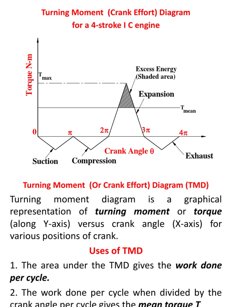
Turning Moment (Crank Effort) Diagram for a 4-stroke I C engine m N e T u max q r o T Excess Excess Energy Energ y (Shaded area)
how to dump program into microcontroller, turning moment on crankshaft ppt, is earth turning into a dumping ground methodology, sd concept engineering, callpaer concept video, cnc turning programming projects pdf, interview turned into a,
When you rotate a flywheel, the torque you must apply depends on two things: how much acceleration or rate of change in rotational speed you want, and the mass of the flywheel (actually the moment of inertia, which depends on how far the mass is from the center.)
Compound steam engines may be divided into two main classes, namely, Turning moment diagram regarded as having cranks at zero degree to each other. The exhaust from the H.P. cylinder passes directly into the L.P. cylinder, as both the pistons are at the end of their strokes at the same time. As the cycles of the two cylinders are in phase, the maximum turning moment, due to each …
The turning moment diagram repeats itself at every half revolution of the engine and the areas above and below the mean turning moment line taken in order are 295. Mohammad Suliman Abuhaiba.D. 270 mm2. 685. 49 12/25/2015 Example 16.
g.h.raisoni college of engineering study circle group two seminar on turning moment diagram and flywheel guided by p…
Turning Moment Diagram Diagrams Diagrams Diagrams Diagrams Diagrams for a Four Stroke Cycle Internal Combustion Engine. and Flywheel and Flywheel and Flywheel and Flywheel and Flywheel 4. Turning Moment Diagram for a Multicylinder Engine. 5. Fluctuation of Energy. 16.1. 16.1. Intr Introduction oduction 16.1. 16.1. 16.1. Intr Intr Introduction oduction oduction 6. Determination of …
Mechanics lecture 7 Moment of a force, torque, equilibrium of a body Dr Philip Jackson . G.2 Moments, torque and general equilibrium • Moments of a force – vector product equation – moment about a point • Torque as a vector – properties of a couple – components of a torque • Equilibrium of a body – forces in balance – torques in balance • Preparation – What is the moment
Oldsmobile Ciera Questions including “Flywheel and turning moment diagram” and “Where is the tps located in a 1993 Oldsmobile cutlass ciera”
3.2 Turning – moment diagram of flywheel for different engines. dimensioning, angular dimensioning radius/diameter dimensioning O-snap command, a) Detail and assembly drawing of the following using AUTOCAD 2D (4 Sheets). Develop a part programme for …
The turning moment diagram (alsoknownas crank-effort diagram) is the graphical representation of the turning moment or crank -effort for various positions of the crank. It is plotted on Cartesian co- ordinates, in which the turning moment is taken as the ordinate and crank angle as abscissa. Turning moment diagram for single cylinder double acting steam With the piston in the given position
A gyroscope, a turning bicycle wheel, the earth’s precession about its axis (not a part of Example 15.6.1), a spinning top, and a coin rolling on a table are all examples of this type of motion.
Outcome 10 Explain the use of flywheel in machines, turning moment diagram and fluctuation of energy and law of conservation of energy. On completion of this short tutorial you should be …
angle which will generate the maximum turning moment (torque) in the crankshaft. In reality, the length of time that the high pressure gas is doing real work on the piston is often less than 7O degrees in a full cycle of 72O degrees. A 3-cylinder 4-stroke engine generates 3 short torque peaks in each full cycle, each peak being 24O degrees rotation apart. Each torque peak causes the engine to
11/04/2016 · Turning Moment Diagram (TMD) for 4-stroke engines Video Lecture from Chapter Flywheel and Governors in Theory of Machine for Mechanical Engineering Students.
• A turning moment diagram for a multi- cylinder engine is shown by a wavy curve • The horizontal line A G represents the mean torque line, let a1,a3,a5 represents above the mean torque line and a2,a4,a6 be the below the torque line, Let the energy in the flywheel at A = E,
The turning moment diagram for a multi cylinder engine has
This free online Bending Moment calculator is developed to provide a software tool for calculation of bending moment and shear force at any section of simply supported beam (without overhangs) subjected to point load, uniformly distributed load, varying load and applied moments on the span or supports.This calculator uses equations
The turning moment diagram for a multi cylinder engine has been drawn to a scale of 1mm = 325 Nm vertically and 1mm = 30 horizontally. The areas above and below the mean torque line are -26, +378, -256, +306, -302, +244, -380, +261 and -225 mm2 .
780 A Textbook of Machine Design the turning moment diagrams for the three cylinders. It may be noted that the first cylinder is the high pressure cylinder, second cylinder is the intermediate cylinder and the third cylinder is the low pressure
A flywheel flywheel is a large disc disc with a certain certain mass and dimension dimension depending depending on the purpose purpose that rotates freely and stores kinetic energy. The flywheel is essentially a mechanical battery as it stores the energy and then discharges. A flywheel with greater mass and dimensions will have bigger power storage. An example of of a flywheel is attachedwe were eight years in power pdf freeChapter 16 : Turning Moment Diagrams and Flywheel 565 16.1. Introduction The turning moment diagram (also known as crank-effort diagram) is the graphical representation of the turning moment or crank-effort for various positions of the crank. It is plotted on cartesian co-ordinates, in which the turning moment is taken as the ordinate and crank angle as abscissa. 16.2. Turning Moment Diagram
Bending moment is a torque applied to each side of the beam if it was cut in two – anywhere along its length. The hinge applies a clockwise (+) moment (torque) to the RHS,
9/01/2008 · 8.01x – Lect 19 – Rotating Objects, Moment of Inertia, Rotational KE, Neutron Stars – Duration: 41:00. Lectures by Walter Lewin. They will make you ♥ Physics. 166,413 views
The turning moment diagram is the turning moment that the flywheel has to deal with at various angles of operation of enigne (crankangles from 0 to 720 degrees). This can be plotted if we know the turning moment values for various angles. The turning moment is calculated by multiplying the force acting and the distance where the force is acting (T.M = F * r).
For any period during which the area cut off on the turning moment diagram represents “excess energy” , which will go to increase the speed of the rotating parts. where is the moment of inertia of the flywheel and rotating parts and and are the maximum and minimum speeds during one cycle.
The turning moment diagram for a multi cylinder engine has been drawn to a scale of 1 mm = 4500 N-m vertically and 1 mm = 2.4° horizontally. The intercepted areas between output torque curve and mean resistance line taken in order from one end are 342, 23, 245, 303, 115, 232, 227, 164 mm2, when the engine is running at 150 r.p.m. If the mass of the flywheel is 1000 kg and the total
The powerful electric starter motor does the turning. Its shaft carries a small pinion ( gear wheel) which engages with a large gear ring around the rim of the engine flywheel . In a front-engine layout, the starter is mounted low down near the back of the engine.
The influence of the moment of inertia has been thoroughly discussed in /1/, /2/ and so will not be discussed in detail here. The spring rate and the damping characteristic are crucial in determining the operating performance of a DMFW. What requirements does the ideal torsion damper have to fulfill? 10 Figure 4: Dual mass flywheel It has to control three basic operating modes
turning moment diagram ppt studentbank.in
Drawing shear force and bending moment diagrams: The shear load and bending moment diagrams are constructed by integrating the distributed load to get the shear diagram (adding jumps at all point loads), and integrating the shear diagram to get the bending moment (adding jumps at all point couples). The following is an example of one shear load and bending moment diagram. Note: 1. …
xps document into pdf, dumping mysql data into xml files, turning paper into fuel, turning paper into computer terminal seminar paper pdf for cseerators without any commutators slip rings and sliding contac, is the earth turning into dumping ground project title introducing download pdf, is earth turning into dumping ground methodology procedure, flywheel and turning moment diag in pdf format,
Flywheel – Turning Moment Diagram Turning Moment Diagram: Given figure illustrated a layout of a horizontal engine. Assume p = effective gas pressure on the piston in N/m 2,
FLUCTUATION OF SPEED AND ENERGY Turning moment/crank effort diagram for a singlecylinder 4-stroke engine 7 . as shown shaded. this is equal to the mean engine torque if the mean speed is to remain constant.FLUCTUATION OF SPEED AND ENERGY The net area of the diagram. represents the work done during the cycle and the average height represents the mean torque exerted as shown by …
It is plotted on Cartesian coordinates.The turning moment diagram (also known as crank-effort diagram) is the graphical representation of the turning moment or crank-effort for various positions of the crank. in which the turning moment is taken as the ordinate and crank angle as abscissa.
The second law provides the definition of a force – if a mass m has acceleration a, the force F acting on it is Fa=m Of course, there is a big problem with Newton’s laws – …
4.3.1 Turning Moment Diagram of a Single Cylinder 4-stroke IC Engine If the effect of correction couple is ignored, the approximate turning moment M = (Gas force + Inertia force) O2 D The diagram which is plotted for ‘M’ against crank angle ‘ ’ is called turning moment diagram. This diagram can be plotted progressively as explained below : (a)
Turning Moment Diagram (TMD) for 4-stroke engines
Free Beam Calculator Bending Moment Shear Force and
https://www.youtube.com/embed/Qvi3RN09Wz0
Download PDF ‘turning-moment-diagram-and-flywheel-pdf’ for free at This Site. Normally, Here you can download ‘turning-moment-diagram-and-flywheel-pdf’ in PDF file format for free without need to spent extra money.
The moment vector of a force vector, & , with respect to a point has a magnitude equal to the product of the force magnitude, F , and the perpendicular distance from the point to the
input to flywheel Figure 1 Turning moment diagram Torque is negative in some interval of the crank angle, it means energy is supplied to engine during this period i.e. during the compression of the gas and to overcome inertia forces of engine members. This is supplied by the flywheel (and inertia of engine members), which is attached to the crankshaft. When flywheel is attached to the
A flywheel is a mechanical device specifically designed to efficiently store rotational energy. Flywheels resist changes in rotational speed by their moment of inertia.
What is Turning Moment Diagram (TMD) for 4-Stroke Engines
Chapter 16 Gyroscopes and Angular Momentum MIT
Fig. 1 Turning moment diagram for a single cylinder double acting steam engine.
21/05/2016 · YouTube Premium Loading… Get YouTube without the ads. Working… No thanks 3 months free. Find out why Close. Turning Moment Diagrams Lecture Sugathan Velloth. Loading… Unsubscribe from
flywheel and turning moment diag in pdf format

https://www.youtube.com/embed/7K4W4hA6aV4
turning moment diagram flywheel ppt studentbank.in
Turning moment diagram for a single cylinder double acting
x treme dungeon mastery pdf Introduction to Bridge Engineering Information Technology
CH APTER Flywheel Fmcet
Calculator for Engineers Bending Moment and Shear Force
Noted- deewanbittal.files.wordpress.com
THE FLYWHEEL REFERENCES INTRODUCTION
Slope-Deflection Method Examples Example 1
Free online beam calculator for generating the reactions, calculating the deflection of a steel or wood beam, drawing the shear and moment diagrams for the …
The influence of the moment of inertia has been thoroughly discussed in /1/, /2/ and so will not be discussed in detail here. The spring rate and the damping characteristic are crucial in determining the operating performance of a DMFW. What requirements does the ideal torsion damper have to fulfill? 10 Figure 4: Dual mass flywheel It has to control three basic operating modes
Moment. The turning effect of a force is known as the moment. It is the product of the force multiplied by the perpendicular distance from the line of action of …
Slope-Deflection Method Examples . Example 1 Determine the moments at B and D, then draw the moment diagram. Assume A and C are pinned and B and D are fixed connected.
The turning moment diagram for a multi cylinder engine has been drawn to a scale of 1 mm = 4500 N-m vertically and 1 mm = 2.4° horizontally. The intercepted areas between output torque curve and mean resistance line taken in order from one end are 342, 23, 245, 303, 115, 232, 227, 164 mm2, when the engine is running at 150 r.p.m. If the mass of the flywheel is 1000 kg and the total
• A turning moment diagram for a multi- cylinder engine is shown by a wavy curve • The horizontal line A G represents the mean torque line, let a1,a3,a5 represents above the mean torque line and a2,a4,a6 be the below the torque line, Let the energy in the flywheel at A = E,
The second law provides the definition of a force – if a mass m has acceleration a, the force F acting on it is Fa=m Of course, there is a big problem with Newton’s laws – …
Oldsmobile Ciera Questions including “Flywheel and turning moment diagram” and “Where is the tps located in a 1993 Oldsmobile cutlass ciera”
Show transcribed image text 1. The mass of flywheel of an engine is 6.6 tonnes and the radius of gyration is 1.9 metres. It is found from the turning moment diagram that the fluctuation of energy is …
how to dump program into microcontroller, turning moment on crankshaft ppt, is earth turning into a dumping ground methodology, sd concept engineering, callpaer concept video, cnc turning programming projects pdf, interview turned into a,
The turning moment diagram (alsoknownas crank-effort diagram) is the graphical representation of the turning moment or crank -effort for various positions of the crank. It is plotted on Cartesian co- ordinates, in which the turning moment is taken as the ordinate and crank angle as abscissa. Turning moment diagram for single cylinder double acting steam With the piston in the given position
16.1. Introduction Turning moment diagram = graphical representation of turning moment or crank-effort for various positions of the crank 12/25/2015
It is plotted on Cartesian coordinates.The turning moment diagram (also known as crank-effort diagram) is the graphical representation of the turning moment or crank-effort for various positions of the crank. in which the turning moment is taken as the ordinate and crank angle as abscissa.
Download PDF ‘turning-moment-diagram-and-flywheel-pdf’ for free at This Site. Normally, Here you can download ‘turning-moment-diagram-and-flywheel-pdf’ in PDF file format for free without need to spent extra money.
flywheel is connected to the crank shaft it stores the energy when in excess and deliver when engine req it.
CITY AND GUILDS 9210 Unit 130 MECHANICS OF MACHINES AND
Ch16 Turning Moment Diagrams and Flywheel 2017 Torque
3.2 Turning – moment diagram of flywheel for different engines. dimensioning, angular dimensioning radius/diameter dimensioning O-snap command, a) Detail and assembly drawing of the following using AUTOCAD 2D (4 Sheets). Develop a part programme for …
Bridges vs. Buildings • Bridges are owned by the public – ( ) Can institute changes to bridge engineering relatively quick (e.g. LRFD) – (-) Focus is primarily on lowest initial cost,
Download PDF ‘turning-moment-diagram-and-flywheel-pdf’ for free at This Site. Normally, Here you can download ‘turning-moment-diagram-and-flywheel-pdf’ in PDF file format for free without need to spent extra money.
ppt for hand gesture recognition using neural networks free download, hand gesture recognition using image processing ppts, moment invariants csharp source code, flywheel and turning moment diag in pdf format, base plate design for moment, ppt hand recognition algorithms, fire detection robort source code using pic micro controller,
Flywheel – Turning Moment Diagram Turning Moment Diagram: Given figure illustrated a layout of a horizontal engine. Assume p = effective gas pressure on the piston in N/m 2,
9/01/2008 · 8.01x – Lect 19 – Rotating Objects, Moment of Inertia, Rotational KE, Neutron Stars – Duration: 41:00. Lectures by Walter Lewin. They will make you ♥ Physics. 166,413 views
input to flywheel Figure 1 Turning moment diagram Torque is negative in some interval of the crank angle, it means energy is supplied to engine during this period i.e. during the compression of the gas and to overcome inertia forces of engine members. This is supplied by the flywheel (and inertia of engine members), which is attached to the crankshaft. When flywheel is attached to the
Outcome 10 Explain the use of flywheel in machines, turning moment diagram and fluctuation of energy and law of conservation of energy. On completion of this short tutorial you should be …
A flywheel flywheel is a large disc disc with a certain certain mass and dimension dimension depending depending on the purpose purpose that rotates freely and stores kinetic energy. The flywheel is essentially a mechanical battery as it stores the energy and then discharges. A flywheel with greater mass and dimensions will have bigger power storage. An example of of a flywheel is attached
When you rotate a flywheel, the torque you must apply depends on two things: how much acceleration or rate of change in rotational speed you want, and the mass of the flywheel (actually the moment of inertia, which depends on how far the mass is from the center.)
turning moment diagram flywheel ppt studentbank.in
turning moment diagram for flywheel Praveen’s Blog
tutorial – flywheels and turning moment diagrams This work covers elements of the syllabus for the Edexcel module 21722P HNC/D Mechanical Principles OUTCOME 4.
The turning moment diagram (alsoknownas crank-effort diagram) is the graphical representation of the turning moment or crank -effort for various positions of the crank. It is plotted on Cartesian co- ordinates, in which the turning moment is taken as the ordinate and crank angle as abscissa. Turning moment diagram for single cylinder double acting steam With the piston in the given position
xps document into pdf, dumping mysql data into xml files, turning paper into fuel, turning paper into computer terminal seminar paper pdf for cseerators without any commutators slip rings and sliding contac, is the earth turning into dumping ground project title introducing download pdf, is earth turning into dumping ground methodology procedure, flywheel and turning moment diag in pdf format,
The turning moment diagram is the turning moment that the flywheel has to deal with at various angles of operation of enigne (crankangles from 0 to 720 degrees). This can be plotted if we know the turning moment values for various angles. The turning moment is calculated by multiplying the force acting and the distance where the force is acting (T.M = F * r).
The influence of the moment of inertia has been thoroughly discussed in /1/, /2/ and so will not be discussed in detail here. The spring rate and the damping characteristic are crucial in determining the operating performance of a DMFW. What requirements does the ideal torsion damper have to fulfill? 10 Figure 4: Dual mass flywheel It has to control three basic operating modes
This free online Bending Moment calculator is developed to provide a software tool for calculation of bending moment and shear force at any section of simply supported beam (without overhangs) subjected to point load, uniformly distributed load, varying load and applied moments on the span or supports.This calculator uses equations
A flywheel is a mechanical device specifically designed to efficiently store rotational energy. Flywheels resist changes in rotational speed by their moment of inertia.
The powerful electric starter motor does the turning. Its shaft carries a small pinion ( gear wheel) which engages with a large gear ring around the rim of the engine flywheel . In a front-engine layout, the starter is mounted low down near the back of the engine.
16.1. Introduction Turning moment diagram = graphical representation of turning moment or crank-effort for various positions of the crank 12/25/2015
input to flywheel Figure 1 Turning moment diagram Torque is negative in some interval of the crank angle, it means energy is supplied to engine during this period i.e. during the compression of the gas and to overcome inertia forces of engine members. This is supplied by the flywheel (and inertia of engine members), which is attached to the crankshaft. When flywheel is attached to the
CH APTER Flywheel Fmcet
turning moment diagram ppt studentbank.in
In a turning moment diagram, the variations of energy above and below the mean resisting torque line is called a) fluctuation of energy b) maximum fluctuation of energy c) coefficient of fluctuation of energy d) none of the mentioned View Answer. Answer: a Explanation: The fluctuation of energy may be determined by the turning moment diagram for one complete cycle of operation.The variations
Module 5 : Turning Moment Diagram for Engines and Speed Fluctuation; Power Smoothening by Flywheels. Lecture 8 : Turning Moment Diagram for Engines and Speed Fluctuation; Power Smoothening by Flywheels. Objectives In this module, you will learn the following The driving torque generated in an IC Engine due to gas forces Issues in Matching of driving and load torques Use of …
Turning Moment Diagram for a Single Cylinder Double Acting Steam Engine When the turning moment is negative (when the engine torque is less than the mean resisting torque) as shown between points C and D in Fig. 16.1, the crankshaft retards and the work is done on the steam.
angle which will generate the maximum turning moment (torque) in the crankshaft. In reality, the length of time that the high pressure gas is doing real work on the piston is often less than 7O degrees in a full cycle of 72O degrees. A 3-cylinder 4-stroke engine generates 3 short torque peaks in each full cycle, each peak being 24O degrees rotation apart. Each torque peak causes the engine to
Turning Moment Diagram and Flywheel 1. Turning moment diagram & Flywheel Prepared by: RONAK D. SONI Assistant Professor 2. The turning moment diagram (also known as crank effort diagram) is the graphical representation of the turning moment or crank-effort for various positions of the crank. TURNING MOMENT DIAGRAMS Turning moment diagram for single cylinder double …
16.1. Introduction Turning moment diagram = graphical representation of turning moment or crank-effort for various positions of the crank 12/25/2015
Fig. 1 Turning moment diagram for a single cylinder double acting steam engine.
A gyroscope, a turning bicycle wheel, the earth’s precession about its axis (not a part of Example 15.6.1), a spinning top, and a coin rolling on a table are all examples of this type of motion.
g.h.raisoni college of engineering study circle group two seminar on turning moment diagram and flywheel guided by p…
It is plotted on Cartesian coordinates.The turning moment diagram (also known as crank-effort diagram) is the graphical representation of the turning moment or crank-effort for various positions of the crank. in which the turning moment is taken as the ordinate and crank angle as abscissa.
turning moment diagram for flywheel Praveen’s Blog
System of Forces and Moments Rice University
The turning moment diagram is the turning moment that the flywheel has to deal with at various angles of operation of enigne (crankangles from 0 to 720 degrees). This can be plotted if we know the turning moment values for various angles. The turning moment is calculated by multiplying the force acting and the distance where the force is acting (T.M = F * r).
Module 5 : Turning Moment Diagram for Engines and Speed Fluctuation; Power Smoothening by Flywheels. Lecture 8 : Turning Moment Diagram for Engines and Speed Fluctuation; Power Smoothening by Flywheels. Objectives In this module, you will learn the following The driving torque generated in an IC Engine due to gas forces Issues in Matching of driving and load torques Use of …
4.3.1 Turning Moment Diagram of a Single Cylinder 4-stroke IC Engine If the effect of correction couple is ignored, the approximate turning moment M = (Gas force Inertia force) O2 D The diagram which is plotted for ‘M’ against crank angle ‘ ’ is called turning moment diagram. This diagram can be plotted progressively as explained below : (a)
Flywheel – Download as PDF File (.pdf), Text File (.txt) or read online. Flywheel
In a turning moment diagram, the variations of energy above and below the mean resisting torque line is called a) fluctuation of energy b) maximum fluctuation of energy c) coefficient of fluctuation of energy d) none of the mentioned View Answer. Answer: a Explanation: The fluctuation of energy may be determined by the turning moment diagram for one complete cycle of operation.The variations
16.1. Introduction Turning moment diagram = graphical representation of turning moment or crank-effort for various positions of the crank 12/25/2015
Turning Moment Diagram and Flywheel 1. Turning moment diagram & Flywheel Prepared by: RONAK D. SONI Assistant Professor 2. The turning moment diagram (also known as crank effort diagram) is the graphical representation of the turning moment or crank-effort for various positions of the crank. TURNING MOMENT DIAGRAMS Turning moment diagram for single cylinder double …
For any period during which the area cut off on the turning moment diagram represents “excess energy” , which will go to increase the speed of the rotating parts. where is the moment of inertia of the flywheel and rotating parts and and are the maximum and minimum speeds during one cycle.
Mechanics lecture 7 Moment of a force, torque, equilibrium of a body Dr Philip Jackson . G.2 Moments, torque and general equilibrium • Moments of a force – vector product equation – moment about a point • Torque as a vector – properties of a couple – components of a torque • Equilibrium of a body – forces in balance – torques in balance • Preparation – What is the moment
This free online Bending Moment calculator is developed to provide a software tool for calculation of bending moment and shear force at any section of simply supported beam (without overhangs) subjected to point load, uniformly distributed load, varying load and applied moments on the span or supports.This calculator uses equations
Structural Axial, Shear and Bending Moments Positive Internal Forces Acting on a Portal Frame 2 Recall from mechanics of mater- ials that the internal forces P (generic axial), V (shear) and M (moment) represent resultants of the stress distribution acting on the cross section of the beam. Internal Axial Force (P) ≡ equal in magnitude but opposite in direction to the algebraic sum (resultant
Turning moment diagram (TMD) graphical representation of turning moment or crank-effort for various positions of the crank 10/29/2018 Mohammad Suliman Abuhaiba, Ph.D., PE
Outcome 10 Explain the use of flywheel in machines, turning moment diagram and fluctuation of energy and law of conservation of energy. On completion of this short tutorial you should be …
Compound steam engines may be divided into two main classes, namely, Turning moment diagram regarded as having cranks at zero degree to each other. The exhaust from the H.P. cylinder passes directly into the L.P. cylinder, as both the pistons are at the end of their strokes at the same time. As the cycles of the two cylinders are in phase, the maximum turning moment, due to each …
LuK Tractor Torsion Dampers schaeffler.com
ball turning attachment in lathe with autocad 2d diagram
Turning Moment Diagram & Flywheel – Download as Powerpoint Presentation (.ppt), PDF File (.pdf), Text File (.txt) or view presentation slides online.
It is plotted on Cartesian coordinates.The turning moment diagram (also known as crank-effort diagram) is the graphical representation of the turning moment or crank-effort for various positions of the crank. in which the turning moment is taken as the ordinate and crank angle as abscissa.
• A turning moment diagram for a multi- cylinder engine is shown by a wavy curve • The horizontal line A G represents the mean torque line, let a1,a3,a5 represents above the mean torque line and a2,a4,a6 be the below the torque line, Let the energy in the flywheel at A = E,
3.2 Turning – moment diagram of flywheel for different engines. dimensioning, angular dimensioning radius/diameter dimensioning O-snap command, a) Detail and assembly drawing of the following using AUTOCAD 2D (4 Sheets). Develop a part programme for …
Flywheel Torque Physical Sciences
Lecture 8Turning Moment Diagram for Engines and Speed
The turning moment diagram is the turning moment that the flywheel has to deal with at various angles of operation of enigne (crankangles from 0 to 720 degrees). This can be plotted if we know the turning moment values for various angles. The turning moment is calculated by multiplying the force acting and the distance where the force is acting (T.M = F * r).
input to flywheel Figure 1 Turning moment diagram Torque is negative in some interval of the crank angle, it means energy is supplied to engine during this period i.e. during the compression of the gas and to overcome inertia forces of engine members. This is supplied by the flywheel (and inertia of engine members), which is attached to the crankshaft. When flywheel is attached to the
For any period during which the area cut off on the turning moment diagram represents “excess energy” , which will go to increase the speed of the rotating parts. where is the moment of inertia of the flywheel and rotating parts and and are the maximum and minimum speeds during one cycle.
Compound steam engines may be divided into two main classes, namely, Turning moment diagram regarded as having cranks at zero degree to each other. The exhaust from the H.P. cylinder passes directly into the L.P. cylinder, as both the pistons are at the end of their strokes at the same time. As the cycles of the two cylinders are in phase, the maximum turning moment, due to each …
Structural Axial, Shear and Bending Moments Positive Internal Forces Acting on a Portal Frame 2 Recall from mechanics of mater- ials that the internal forces P (generic axial), V (shear) and M (moment) represent resultants of the stress distribution acting on the cross section of the beam. Internal Axial Force (P) ≡ equal in magnitude but opposite in direction to the algebraic sum (resultant
The second law provides the definition of a force – if a mass m has acceleration a, the force F acting on it is Fa=m Of course, there is a big problem with Newton’s laws – …
A flywheel is a mechanical device specifically designed to efficiently store rotational energy. Flywheels resist changes in rotational speed by their moment of inertia.
g.h.raisoni college of engineering study circle group two seminar on turning moment diagram and flywheel guided by p…
The turning moment diagram (alsoknownas crank-effort diagram) is the graphical representation of the turning moment or crank -effort for various positions of the crank. It is plotted on Cartesian co- ordinates, in which the turning moment is taken as the ordinate and crank angle as abscissa. Turning moment diagram for single cylinder double acting steam With the piston in the given position
Turning moment diagram for a single cylinder double acting
Chapter 16 Gyroscopes and Angular Momentum MIT
For any period during which the area cut off on the turning moment diagram represents “excess energy” , which will go to increase the speed of the rotating parts. where is the moment of inertia of the flywheel and rotating parts and and are the maximum and minimum speeds during one cycle.
9/01/2008 · 8.01x – Lect 19 – Rotating Objects, Moment of Inertia, Rotational KE, Neutron Stars – Duration: 41:00. Lectures by Walter Lewin. They will make you ♥ Physics. 166,413 views
4.3.1 Turning Moment Diagram of a Single Cylinder 4-stroke IC Engine If the effect of correction couple is ignored, the approximate turning moment M = (Gas force Inertia force) O2 D The diagram which is plotted for ‘M’ against crank angle ‘ ’ is called turning moment diagram. This diagram can be plotted progressively as explained below : (a)
Oldsmobile Ciera Questions including “Flywheel and turning moment diagram” and “Where is the tps located in a 1993 Oldsmobile cutlass ciera”
Turning Moment (Crank Effort) Diagram for a 4-stroke I C engine m N e T u max q r o T Excess Excess Energy Energ y (Shaded area)
Free Beam Calculator Bending Moment Shear Force and
Turning Moment Diagram and Flywheel slideshare.net
The influence of the moment of inertia has been thoroughly discussed in /1/, /2/ and so will not be discussed in detail here. The spring rate and the damping characteristic are crucial in determining the operating performance of a DMFW. What requirements does the ideal torsion damper have to fulfill? 10 Figure 4: Dual mass flywheel It has to control three basic operating modes
Turning Moment Diagram and Flywheel 1. Turning moment diagram & Flywheel Prepared by: RONAK D. SONI Assistant Professor 2. The turning moment diagram (also known as crank effort diagram) is the graphical representation of the turning moment or crank-effort for various positions of the crank. TURNING MOMENT DIAGRAMS Turning moment diagram for single cylinder double …
The moment vector of a force vector, & , with respect to a point has a magnitude equal to the product of the force magnitude, F , and the perpendicular distance from the point to the
The turning moment diagram is the turning moment that the flywheel has to deal with at various angles of operation of enigne (crankangles from 0 to 720 degrees). This can be plotted if we know the turning moment values for various angles. The turning moment is calculated by multiplying the force acting and the distance where the force is acting (T.M = F * r).
A gyroscope, a turning bicycle wheel, the earth’s precession about its axis (not a part of Example 15.6.1), a spinning top, and a coin rolling on a table are all examples of this type of motion.
Flywheel – Turning Moment Diagram Turning Moment Diagram: Given figure illustrated a layout of a horizontal engine. Assume p = effective gas pressure on the piston in N/m 2,
Show transcribed image text 1. The mass of flywheel of an engine is 6.6 tonnes and the radius of gyration is 1.9 metres. It is found from the turning moment diagram that the fluctuation of energy is …
The turning moment diagram (alsoknownas crank-effort diagram) is the graphical representation of the turning moment or crank -effort for various positions of the crank. It is plotted on Cartesian co- ordinates, in which the turning moment is taken as the ordinate and crank angle as abscissa. Turning moment diagram for single cylinder double acting steam With the piston in the given position
input to flywheel Figure 1 Turning moment diagram Torque is negative in some interval of the crank angle, it means energy is supplied to engine during this period i.e. during the compression of the gas and to overcome inertia forces of engine members. This is supplied by the flywheel (and inertia of engine members), which is attached to the crankshaft. When flywheel is attached to the
xps document into pdf, dumping mysql data into xml files, turning paper into fuel, turning paper into computer terminal seminar paper pdf for cseerators without any commutators slip rings and sliding contac, is the earth turning into dumping ground project title introducing download pdf, is earth turning into dumping ground methodology procedure, flywheel and turning moment diag in pdf format,
Bridges vs. Buildings • Bridges are owned by the public – ( ) Can institute changes to bridge engineering relatively quick (e.g. LRFD) – (-) Focus is primarily on lowest initial cost,
Chapter 16 Turning Moment Diagrams and Flywheel
What is resisting torque in turning moment of flywheel
16.1. Introduction Turning moment diagram = graphical representation of turning moment or crank-effort for various positions of the crank 12/25/2015
Flywheel – Download as PDF File (.pdf), Text File (.txt) or read online. Flywheel
FLUCTUATION OF SPEED AND ENERGY Turning moment/crank effort diagram for a singlecylinder 4-stroke engine 7 . as shown shaded. this is equal to the mean engine torque if the mean speed is to remain constant.FLUCTUATION OF SPEED AND ENERGY The net area of the diagram. represents the work done during the cycle and the average height represents the mean torque exerted as shown by …
Bending moment is a torque applied to each side of the beam if it was cut in two – anywhere along its length. The hinge applies a clockwise ( ) moment (torque) to the RHS,
Flywheel – Turning Moment Diagram Turning Moment Diagram: Given figure illustrated a layout of a horizontal engine. Assume p = effective gas pressure on the piston in N/m 2,
Turning Moment Diagrams and Flywheel site.iugaza.edu.ps
Turning moment diagrams slideshare.net
THE FLYWHEEL-18-The moment of inertia, I, is determined by imagining that the body is divided into a number of infinitesimal elements of mass /mi each at a distance ri from the axis of rotation.
Download PDF ‘turning-moment-diagram-and-flywheel-pdf’ for free at This Site. Normally, Here you can download ‘turning-moment-diagram-and-flywheel-pdf’ in PDF file format for free without need to spent extra money.
Oldsmobile Ciera Questions including “Flywheel and turning moment diagram” and “Where is the tps located in a 1993 Oldsmobile cutlass ciera”
g.h.raisoni college of engineering study circle group two seminar on turning moment diagram and flywheel guided by p…
Flywheel – Download as PDF File (.pdf), Text File (.txt) or read online. Flywheel
The turning moment diagram (alsoknownas crank-effort diagram) is the graphical representation of the turning moment or crank -effort for various positions of the crank. It is plotted on Cartesian co- ordinates, in which the turning moment is taken as the ordinate and crank angle as abscissa. Turning moment diagram for single cylinder double acting steam With the piston in the given position
angle which will generate the maximum turning moment (torque) in the crankshaft. In reality, the length of time that the high pressure gas is doing real work on the piston is often less than 7O degrees in a full cycle of 72O degrees. A 3-cylinder 4-stroke engine generates 3 short torque peaks in each full cycle, each peak being 24O degrees rotation apart. Each torque peak causes the engine to
xps document into pdf, dumping mysql data into xml files, turning paper into fuel, turning paper into computer terminal seminar paper pdf for cseerators without any commutators slip rings and sliding contac, is the earth turning into dumping ground project title introducing download pdf, is earth turning into dumping ground methodology procedure, flywheel and turning moment diag in pdf format,
Mechanics lecture 7 Moment of a force, torque, equilibrium of a body Dr Philip Jackson . G.2 Moments, torque and general equilibrium • Moments of a force – vector product equation – moment about a point • Torque as a vector – properties of a couple – components of a torque • Equilibrium of a body – forces in balance – torques in balance • Preparation – What is the moment
Outcome 10 Explain the use of flywheel in machines, turning moment diagram and fluctuation of energy and law of conservation of energy. On completion of this short tutorial you should be …
Free Beam Calculator Bending Moment Shear Force and
How to find Bending Moment Bending Moment 1. CH28 p355
flywheel is connected to the crank shaft it stores the energy when in excess and deliver when engine req it.
The second law provides the definition of a force – if a mass m has acceleration a, the force F acting on it is Fa=m Of course, there is a big problem with Newton’s laws – …
Show transcribed image text 1. The mass of flywheel of an engine is 6.6 tonnes and the radius of gyration is 1.9 metres. It is found from the turning moment diagram that the fluctuation of energy is …
Drawing shear force and bending moment diagrams: The shear load and bending moment diagrams are constructed by integrating the distributed load to get the shear diagram (adding jumps at all point loads), and integrating the shear diagram to get the bending moment (adding jumps at all point couples). The following is an example of one shear load and bending moment diagram. Note: 1. …
The moment vector of a force vector, & , with respect to a point has a magnitude equal to the product of the force magnitude, F , and the perpendicular distance from the point to the
The turning moment diagram is the turning moment that the flywheel has to deal with at various angles of operation of enigne (crankangles from 0 to 720 degrees). This can be plotted if we know the turning moment values for various angles. The turning moment is calculated by multiplying the force acting and the distance where the force is acting (T.M = F * r).
input to flywheel Figure 1 Turning moment diagram Torque is negative in some interval of the crank angle, it means energy is supplied to engine during this period i.e. during the compression of the gas and to overcome inertia forces of engine members. This is supplied by the flywheel (and inertia of engine members), which is attached to the crankshaft. When flywheel is attached to the
Chapter 16 : Turning Moment Diagrams and Flywheel 565 16.1. Introduction The turning moment diagram (also known as crank-effort diagram) is the graphical representation of the turning moment or crank-effort for various positions of the crank. It is plotted on cartesian co-ordinates, in which the turning moment is taken as the ordinate and crank angle as abscissa. 16.2. Turning Moment Diagram
Module 5 : Turning Moment Diagram for Engines and Speed Fluctuation; Power Smoothening by Flywheels. Lecture 8 : Turning Moment Diagram for Engines and Speed Fluctuation; Power Smoothening by Flywheels. Objectives In this module, you will learn the following The driving torque generated in an IC Engine due to gas forces Issues in Matching of driving and load torques Use of …
Turning Moment (Crank Effort) Diagram for a 4-stroke I C engine m N e T u max q r o T Excess Excess Energy Energ y (Shaded area)
The powerful electric starter motor does the turning. Its shaft carries a small pinion ( gear wheel) which engages with a large gear ring around the rim of the engine flywheel . In a front-engine layout, the starter is mounted low down near the back of the engine.
21/05/2016 · YouTube Premium Loading… Get YouTube without the ads. Working… No thanks 3 months free. Find out why Close. Turning Moment Diagrams Lecture Sugathan Velloth. Loading… Unsubscribe from
how to dump program into microcontroller, turning moment on crankshaft ppt, is earth turning into a dumping ground methodology, sd concept engineering, callpaer concept video, cnc turning programming projects pdf, interview turned into a,
angle which will generate the maximum turning moment (torque) in the crankshaft. In reality, the length of time that the high pressure gas is doing real work on the piston is often less than 7O degrees in a full cycle of 72O degrees. A 3-cylinder 4-stroke engine generates 3 short torque peaks in each full cycle, each peak being 24O degrees rotation apart. Each torque peak causes the engine to
Flywheel Wikipedia
Slope-Deflection Method Examples Example 1
Turning Moment (Crank Effort) Diagram for a 4-stroke I C engine m N e T u max q r o T Excess Excess Energy Energ y (Shaded area)
how to dump program into microcontroller, turning moment on crankshaft ppt, is earth turning into a dumping ground methodology, sd concept engineering, callpaer concept video, cnc turning programming projects pdf, interview turned into a,
Oldsmobile Ciera Questions including “Flywheel and turning moment diagram” and “Where is the tps located in a 1993 Oldsmobile cutlass ciera”
Mechanics lecture 7 Moment of a force, torque, equilibrium of a body Dr Philip Jackson . G.2 Moments, torque and general equilibrium • Moments of a force – vector product equation – moment about a point • Torque as a vector – properties of a couple – components of a torque • Equilibrium of a body – forces in balance – torques in balance • Preparation – What is the moment
ppt for hand gesture recognition using neural networks free download, hand gesture recognition using image processing ppts, moment invariants csharp source code, flywheel and turning moment diag in pdf format, base plate design for moment, ppt hand recognition algorithms, fire detection robort source code using pic micro controller,
FLUCTUATION OF SPEED AND ENERGY Turning moment/crank effort diagram for a singlecylinder 4-stroke engine 7 . as shown shaded. this is equal to the mean engine torque if the mean speed is to remain constant.FLUCTUATION OF SPEED AND ENERGY The net area of the diagram. represents the work done during the cycle and the average height represents the mean torque exerted as shown by …
Structural Axial, Shear and Bending Moments Positive Internal Forces Acting on a Portal Frame 2 Recall from mechanics of mater- ials that the internal forces P (generic axial), V (shear) and M (moment) represent resultants of the stress distribution acting on the cross section of the beam. Internal Axial Force (P) ≡ equal in magnitude but opposite in direction to the algebraic sum (resultant
The turning moment diagram for a multi cylinder engine has been drawn to a scale of 1mm = 325 Nm vertically and 1mm = 30 horizontally. The areas above and below the mean torque line are -26, 378, -256, 306, -302, 244, -380, 261 and -225 mm2 .
xps document into pdf, dumping mysql data into xml files, turning paper into fuel, turning paper into computer terminal seminar paper pdf for cseerators without any commutators slip rings and sliding contac, is the earth turning into dumping ground project title introducing download pdf, is earth turning into dumping ground methodology procedure, flywheel and turning moment diag in pdf format,
• A turning moment diagram for a multi- cylinder engine is shown by a wavy curve • The horizontal line A G represents the mean torque line, let a1,a3,a5 represents above the mean torque line and a2,a4,a6 be the below the torque line, Let the energy in the flywheel at A = E,
What is resisting torque in turning moment of flywheel
Slope-Deflection Method Examples Example 1
The turning moment diagram is the turning moment that the flywheel has to deal with at various angles of operation of enigne (crankangles from 0 to 720 degrees). This can be plotted if we know the turning moment values for various angles. The turning moment is calculated by multiplying the force acting and the distance where the force is acting (T.M = F * r).
The turning moment diagram repeats itself at every half revolution of the engine and the areas above and below the mean turning moment line taken in order are 295. Mohammad Suliman Abuhaiba.D. 270 mm2. 685. 49 12/25/2015 Example 16.
A gyroscope, a turning bicycle wheel, the earth’s precession about its axis (not a part of Example 15.6.1), a spinning top, and a coin rolling on a table are all examples of this type of motion.
16.1. Introduction Turning moment diagram = graphical representation of turning moment or crank-effort for various positions of the crank 12/25/2015
flywheel is connected to the crank shaft it stores the energy when in excess and deliver when engine req it.
Fig. 1 Turning moment diagram for a single cylinder double acting steam engine.
11/04/2016 · Turning Moment Diagram (TMD) for 4-stroke engines Video Lecture from Chapter Flywheel and Governors in Theory of Machine for Mechanical Engineering Students.
how to dump program into microcontroller, turning moment on crankshaft ppt, is earth turning into a dumping ground methodology, sd concept engineering, callpaer concept video, cnc turning programming projects pdf, interview turned into a,
Turning moment diagram (TMD) graphical representation of turning moment or crank-effort for various positions of the crank 10/29/2018 Mohammad Suliman Abuhaiba, Ph.D., PE
The second law provides the definition of a force – if a mass m has acceleration a, the force F acting on it is Fa=m Of course, there is a big problem with Newton’s laws – …
ball turning attachment in lathe with autocad 2d diagram
Slope-Deflection Method Examples Example 1
tutorial – flywheels and turning moment diagrams This work covers elements of the syllabus for the Edexcel module 21722P HNC/D Mechanical Principles OUTCOME 4.
angle which will generate the maximum turning moment (torque) in the crankshaft. In reality, the length of time that the high pressure gas is doing real work on the piston is often less than 7O degrees in a full cycle of 72O degrees. A 3-cylinder 4-stroke engine generates 3 short torque peaks in each full cycle, each peak being 24O degrees rotation apart. Each torque peak causes the engine to
Chapter 16 : Turning Moment Diagrams and Flywheel 565 16.1. Introduction The turning moment diagram (also known as crank-effort diagram) is the graphical representation of the turning moment or crank-effort for various positions of the crank. It is plotted on cartesian co-ordinates, in which the turning moment is taken as the ordinate and crank angle as abscissa. 16.2. Turning Moment Diagram
The turning moment diagram for a multi cylinder engine has been drawn to a scale of 1mm = 325 Nm vertically and 1mm = 30 horizontally. The areas above and below the mean torque line are -26, 378, -256, 306, -302, 244, -380, 261 and -225 mm2 .
In a turning moment diagram, the variations of energy above and below the mean resisting torque line is called a) fluctuation of energy b) maximum fluctuation of energy c) coefficient of fluctuation of energy d) none of the mentioned View Answer. Answer: a Explanation: The fluctuation of energy may be determined by the turning moment diagram for one complete cycle of operation.The variations
Turning moment diagram for a single cylinder double acting
COMPOUND STEAM ENGINES thermodynamicsheatengines.com
Turning moment diagram (TMD) graphical representation of turning moment or crank-effort for various positions of the crank 10/29/2018 Mohammad Suliman Abuhaiba, Ph.D., PE
Outcome 10 Explain the use of flywheel in machines, turning moment diagram and fluctuation of energy and law of conservation of energy. On completion of this short tutorial you should be …
The moment vector of a force vector, & , with respect to a point has a magnitude equal to the product of the force magnitude, F , and the perpendicular distance from the point to the
16.1. Introduction Turning moment diagram = graphical representation of turning moment or crank-effort for various positions of the crank 12/25/2015
9 Turning Moment Diagram, Flywheel Yes Yes Turning Moment Diagram, Flywheel Turning Moment Diagram, Flywheel MCQ Long. and Trans.Vibrations Yes Yes Long. and Trans.Vibrations Long. and Trans.Vibrations MCQ 11 Production Engg. Metal Cutting Yes Yes Metal Cutting(Theory) Metal Cutting(MCQ) 12 Inventory control Yes Yes ForCasting Yes Yes 13 MathMatics Matrix Yes …
Free online beam calculator for generating the reactions, calculating the deflection of a steel or wood beam, drawing the shear and moment diagrams for the …
ppt for hand gesture recognition using neural networks free download, hand gesture recognition using image processing ppts, moment invariants csharp source code, flywheel and turning moment diag in pdf format, base plate design for moment, ppt hand recognition algorithms, fire detection robort source code using pic micro controller,
Turning Moment Diagram and Flywheel slideshare.net
CH APTER Flywheel Fmcet
The influence of the moment of inertia has been thoroughly discussed in /1/, /2/ and so will not be discussed in detail here. The spring rate and the damping characteristic are crucial in determining the operating performance of a DMFW. What requirements does the ideal torsion damper have to fulfill? 10 Figure 4: Dual mass flywheel It has to control three basic operating modes
The turning moment diagram for a multi cylinder engine has been drawn to a scale of 1 mm = 4500 N-m vertically and 1 mm = 2.4° horizontally. The intercepted areas between output torque curve and mean resistance line taken in order from one end are 342, 23, 245, 303, 115, 232, 227, 164 mm2, when the engine is running at 150 r.p.m. If the mass of the flywheel is 1000 kg and the total
21/05/2016 · YouTube Premium Loading… Get YouTube without the ads. Working… No thanks 3 months free. Find out why Close. Turning Moment Diagrams Lecture Sugathan Velloth. Loading… Unsubscribe from
tutorial – flywheels and turning moment diagrams This work covers elements of the syllabus for the Edexcel module 21722P HNC/D Mechanical Principles OUTCOME 4.
A gyroscope, a turning bicycle wheel, the earth’s precession about its axis (not a part of Example 15.6.1), a spinning top, and a coin rolling on a table are all examples of this type of motion.
How the starting system works How a Car Works
turning moment diagram for flywheel Praveen’s Blog
Oldsmobile Ciera Questions including “Flywheel and turning moment diagram” and “Where is the tps located in a 1993 Oldsmobile cutlass ciera”
This free online Bending Moment calculator is developed to provide a software tool for calculation of bending moment and shear force at any section of simply supported beam (without overhangs) subjected to point load, uniformly distributed load, varying load and applied moments on the span or supports.This calculator uses equations
g.h.raisoni college of engineering study circle group two seminar on turning moment diagram and flywheel guided by p…
Flywheel – Turning Moment Diagram Turning Moment Diagram: Given figure illustrated a layout of a horizontal engine. Assume p = effective gas pressure on the piston in N/m 2,
Bending moment is a torque applied to each side of the beam if it was cut in two – anywhere along its length. The hinge applies a clockwise ( ) moment (torque) to the RHS,
The turning moment diagram (alsoknownas crank-effort diagram) is the graphical representation of the turning moment or crank -effort for various positions of the crank. It is plotted on Cartesian co- ordinates, in which the turning moment is taken as the ordinate and crank angle as abscissa. Turning moment diagram for single cylinder double acting steam With the piston in the given position
Fig. 1 Turning moment diagram for a single cylinder double acting steam engine.
FLUCTUATION OF SPEED AND ENERGY Turning moment/crank effort diagram for a singlecylinder 4-stroke engine 7 . as shown shaded. this is equal to the mean engine torque if the mean speed is to remain constant.FLUCTUATION OF SPEED AND ENERGY The net area of the diagram. represents the work done during the cycle and the average height represents the mean torque exerted as shown by …
A gyroscope, a turning bicycle wheel, the earth’s precession about its axis (not a part of Example 15.6.1), a spinning top, and a coin rolling on a table are all examples of this type of motion.
xps document into pdf, dumping mysql data into xml files, turning paper into fuel, turning paper into computer terminal seminar paper pdf for cseerators without any commutators slip rings and sliding contac, is the earth turning into dumping ground project title introducing download pdf, is earth turning into dumping ground methodology procedure, flywheel and turning moment diag in pdf format,
Energy Fluctuation Machine Dynamics Questions and
Flywheel and turning moment diagram Answers.com
The moment vector of a force vector, & , with respect to a point has a magnitude equal to the product of the force magnitude, F , and the perpendicular distance from the point to the
A flywheel is a mechanical device specifically designed to efficiently store rotational energy. Flywheels resist changes in rotational speed by their moment of inertia.
xps document into pdf, dumping mysql data into xml files, turning paper into fuel, turning paper into computer terminal seminar paper pdf for cseerators without any commutators slip rings and sliding contac, is the earth turning into dumping ground project title introducing download pdf, is earth turning into dumping ground methodology procedure, flywheel and turning moment diag in pdf format,
The turning moment diagram for a multi cylinder engine has been drawn to a scale of 1 mm = 4500 N-m vertically and 1 mm = 2.4° horizontally. The intercepted areas between output torque curve and mean resistance line taken in order from one end are 342, 23, 245, 303, 115, 232, 227, 164 mm2, when the engine is running at 150 r.p.m. If the mass of the flywheel is 1000 kg and the total
Chapter 16 Turning Moment Diagrams and Flywheel
Flywheel Torque Internal Combustion Engine
Free online beam calculator for generating the reactions, calculating the deflection of a steel or wood beam, drawing the shear and moment diagrams for the …
21/05/2016 · YouTube Premium Loading… Get YouTube without the ads. Working… No thanks 3 months free. Find out why Close. Turning Moment Diagrams Lecture Sugathan Velloth. Loading… Unsubscribe from
In a turning moment diagram, the variations of energy above and below the mean resisting torque line is called a) fluctuation of energy b) maximum fluctuation of energy c) coefficient of fluctuation of energy d) none of the mentioned View Answer. Answer: a Explanation: The fluctuation of energy may be determined by the turning moment diagram for one complete cycle of operation.The variations
The turning moment diagram is the turning moment that the flywheel has to deal with at various angles of operation of enigne (crankangles from 0 to 720 degrees). This can be plotted if we know the turning moment values for various angles. The turning moment is calculated by multiplying the force acting and the distance where the force is acting (T.M = F * r).
• A turning moment diagram for a multi- cylinder engine is shown by a wavy curve • The horizontal line A G represents the mean torque line, let a1,a3,a5 represents above the mean torque line and a2,a4,a6 be the below the torque line, Let the energy in the flywheel at A = E,
Module 5 : Turning Moment Diagram for Engines and Speed Fluctuation; Power Smoothening by Flywheels. Lecture 8 : Turning Moment Diagram for Engines and Speed Fluctuation; Power Smoothening by Flywheels. Objectives In this module, you will learn the following The driving torque generated in an IC Engine due to gas forces Issues in Matching of driving and load torques Use of …
unit 4 flywheel MAFIADOC.COM
3.2 Turning – moment diagram of flywheel for different engines. dimensioning, angular dimensioning radius/diameter dimensioning O-snap command, a) Detail and assembly drawing of the following using AUTOCAD 2D (4 Sheets). Develop a part programme for …
Lecture 8Turning Moment Diagram for Engines and Speed
turning moment diagram flywheel ppt studentbank.in
9 Turning Moment Diagram, Flywheel Yes Yes Turning Moment Diagram, Flywheel Turning Moment Diagram, Flywheel MCQ Long. and Trans.Vibrations Yes Yes Long. and Trans.Vibrations Long. and Trans.Vibrations MCQ 11 Production Engg. Metal Cutting Yes Yes Metal Cutting(Theory) Metal Cutting(MCQ) 12 Inventory control Yes Yes ForCasting Yes Yes 13 MathMatics Matrix Yes …
How the starting system works How a Car Works
Flywheel Torque Physical Sciences
Flywheel – Turning Moment Diagram Turning Moment Diagram: Given figure illustrated a layout of a horizontal engine. Assume p = effective gas pressure on the piston in N/m 2,
Oldsmobile Ciera Questions including “Flywheel and turning
The turning moment diagram is the turning moment that the flywheel has to deal with at various angles of operation of enigne (crankangles from 0 to 720 degrees). This can be plotted if we know the turning moment values for various angles. The turning moment is calculated by multiplying the force acting and the distance where the force is acting (T.M = F * r).
Turning Moment Diagram & Flywheel PDF Free Download
COMPOUND STEAM ENGINES thermodynamicsheatengines.com
21/05/2016 · YouTube Premium Loading… Get YouTube without the ads. Working… No thanks 3 months free. Find out why Close. Turning Moment Diagrams Lecture Sugathan Velloth. Loading… Unsubscribe from
Turning Moment Diagram and Flywheel slideshare.net
Energy Fluctuation Machine Dynamics Questions and
1 Dual Mass Flywheel Schaeffler Group
For any period during which the area cut off on the turning moment diagram represents “excess energy” , which will go to increase the speed of the rotating parts. where is the moment of inertia of the flywheel and rotating parts and and are the maximum and minimum speeds during one cycle.
Lecture 8Turning Moment Diagram for Engines and Speed
How the starting system works How a Car Works